The practical result of the transition to servicing equipment in technical condition at the enterprise LLC Tomskneftekhim
It is always interesting to get acquainted with the results of the work of colleagues from other enterprises. See what problems they face, what tasks they have to solve. Unfortunately, in the field of technical diagnostics, specialists are in no hurry to share their experience and knowledge. Therefore, with special thanks to colleagues from Tomskneftekhim, I propose to look at examples from their practical activities.

Introduction
Reliable operation of the main and auxiliary equipment is currently not possible without periodic vibration monitoring and vibration diagnostics of its condition. The main defects in parts and assemblies arise during the operation and repair of equipment. Some defects - such as natural physical wear and tear - are objective, but many defects are “man-made” and are someone’s defect both during repair, during operation, and during manufacturing and incoming inspection.
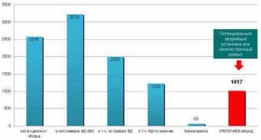
We in Tomsk are trying to study and systematize the causes of increased equipment vibration in order to understand the true situation that has developed with our dynamic equipment. The analysis of the main defects detected during the equipment diagnostics during 2011 is presented in diagram 1.
Chart 1.
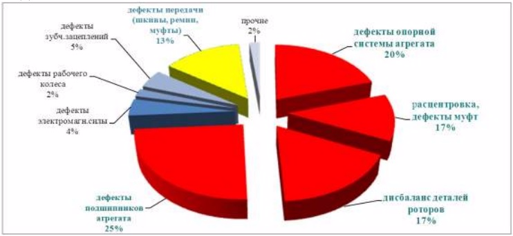
I would like to offer you some practical examples of identifying the most common defects, which are mainly typical for
this type of equipment. Descriptions of several particularly important units, protocols for their diagnosis and the procedure for eliminating defects are given. Only defects with a level of development not lower than average are listed in the protocols.
In preparing this material, the experience of the author and his colleagues in the application of the developed measures to increase the reliability of real operated machines in our enterprise.
On the unit diagram, the designations В, Г, and О are used to indicate the direction of measurements of RMS vibrational velocities, respectively: vertical, horizontal and axial, and their
values in mm / sec. In order to provide a compact report, the following are provided:
- reduction in fragments of vibration diagnostics protocols with the ratings “Permissible” and “Permissible after repair”;
- additional recommendations and comments on the need for viromonitoring of this equipment and its frequency;
- the numbers indicate the numbers of the supports;
- EM - electric motor;
- RMS - mean square value;
- CMVP - control measurements of vibration parameters.
Example 1.
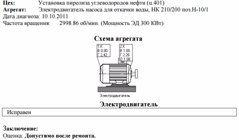
1.1 After repairing the electric motor and installing it at a technological position before aligning the shafts and connecting to the pump, a vibratory inspection of the electric motor was carried out.
Fragment of the diagnostic protocol
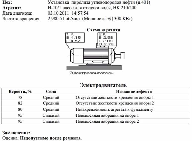
Comments:
Measurements of vibration in real time showed that the level of the RMS of vibration velocity in the horizontal direction is not stable and varies from
3 mm / s to 6 mm / s, with a frequency of 1 minute, while the vibration in the vertical direction (4.1 mm / s) practically does not change.
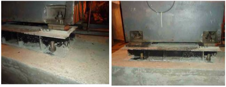
Conducted research activities allow us to make the assumption that a high level of vibration and its instability in the horizontal direction are a consequence of the insufficient area of the supporting surface of the legs of the electric motor.
As a result of the “forced” pulling of the paws, the motor casing was deformed, which leads to high levels of vibration.
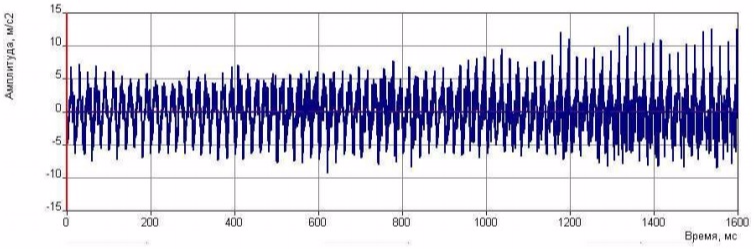
Fig. 1. The vibration acceleration signal of 1 kHz support 1 horizontal direction.
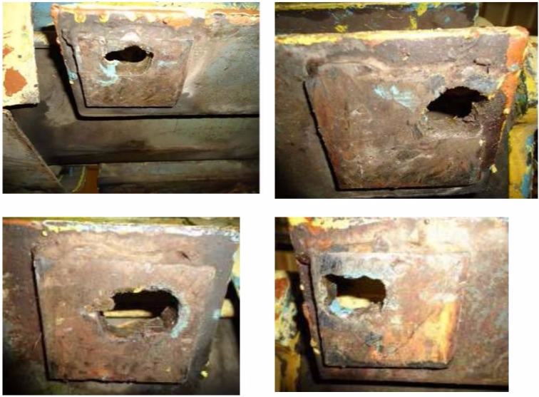
Recommendations:
Increase the abutment surface of the foot of the motor to the frame.
Fig. 2. Photo of the supporting surfaces of the legs of the electric motor.
1.2 The state of the unit after additional measures (completion of the supporting surface of the paws), initiated by the vibrodiagnostic group.
Fragment of the diagnostic protocol
Example 2.
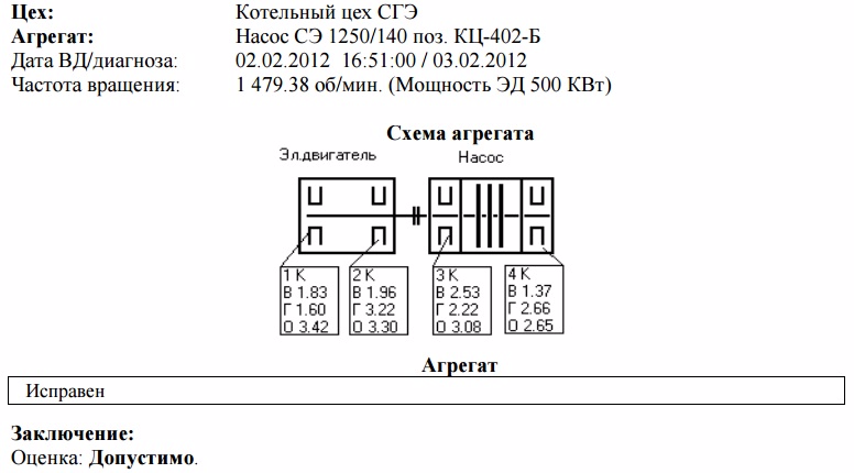
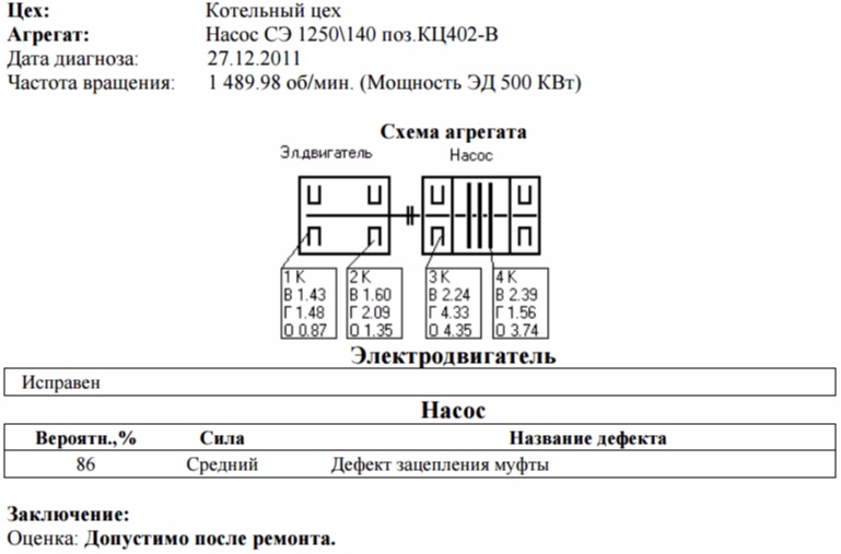
2.1 Diagnostics of the network pump SE 1250 \ 140 pos.402.B was carried out according to the schedule of vibration diagnostics before repair.
Fragment of the diagnostic protocol
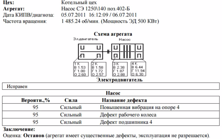
Comments:
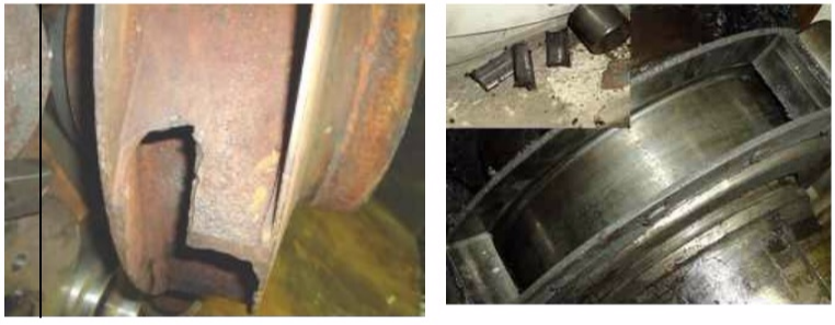
The main reasons for increased vibration of the unit are: a defect in the impeller of the pump (see Fig. 5), a defect in the bearing of bearing No. 4 (see. Fig. 5).
Fig. 3. The SKZ spectrum of vibration speeds of the support No. 4 is the axial direction.
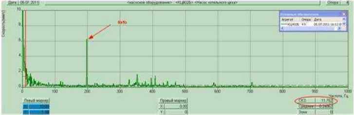
The main contribution to the increased vibration value of the unit is made by the eighth harmonic of the working frequency (198.13 Hz), which indicates a defect in the impeller of the pump.
Fig. 4. Acceleration spectra from 10 to 10 000 Hz. Bearing support No. 4 - horizontal direction.
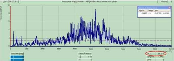
The RMS value of vibration acceleration is 68 m / s², which indicates the development of friction in the bearing assembly of the support 4.
Recommendations:
Replace the bearing of the support 4, repair / replace the impeller of the pump.
Fig. 5. Photo of a dismantled impeller with a defect of one blade (left) and bearing support 4 (right).
2.2 Condition of the unit after additional measures (bearing replacement, wheel replacement), initiated by the vibration diagnostics group.
Fragment of the diagnostic protocol
Example 3.
3.1. Diagnosis was carried out at the request of the installation mechanic, the cause of which was the increased vibration of the unit.
Fragment of the diagnostic protocol
Comments:
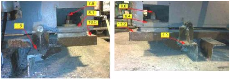
The main reason for the increased vibration of the unit is the lack of rigidity of its support system (there are mechanical loosening of the unit mounting in the bolt-paw-frame system, as well as the frame-anchor-foundation system). A contour diagram of the distribution of vibration along the supporting structure of the unit is shown in Fig. 6.
Fig. 6. Contour diagram of the distribution of vibration along the supporting structure of the unit.
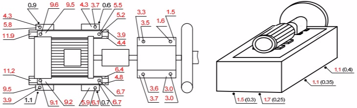
High RMS values of vibration velocity (Ve - mm / s) in the bolt-paw-frame system indicate that there is a significant weakening of the support system of the unit.
The RMS value of the vibration velocity along the perimeter of the foundation block is in the range 1.1 ÷ 1.7 mm / s, for example, at the same points along the perimeter of the foundation block of the neighboring unit (blower pos. 5010.2) the vibration is 0.25 ÷ 0.4 mm / s, which is about 3 ÷ 5 times less. In the diagram, the RMS values of the vibration velocity for the unit 5010.2 are indicated in parentheses.
Fig. 7. Photo of the supporting structure of the GRF300 / 1150 5010.1 blower before repair.
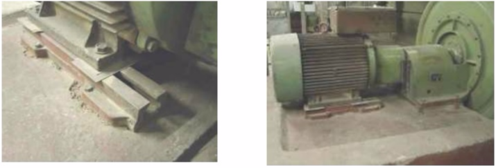
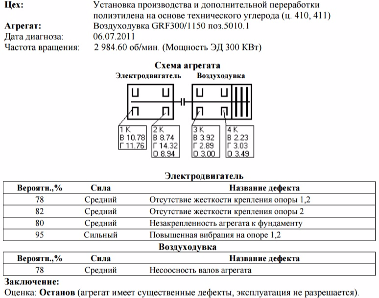
Fig. 8. Spectrum of vibration acceleration. Support No. 2 - the vertical direction.
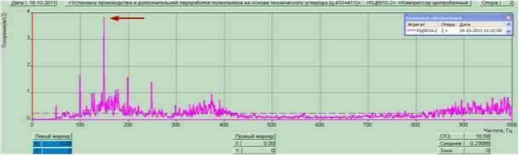
The third revolving frequency (3fo) of the electric motor rotor dominates in the vibration acceleration spectrum, which indicates insufficient rigidity of the support system.
Recommendations:
Ensure rigidity of the unit support structure. Replace anchor bolts under supports No. 1 and No. 2 of the electric motor. Make a broach of all the bolted connections of the unit bed to the frame (by supports: 1, 2, 3, 4).
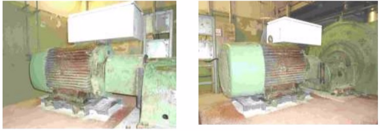
3.2. The state of the unit after carrying out additional measures (see above in the recommendations) initiated by the vibration diagnostics group.
Fragment of the diagnostic protocol
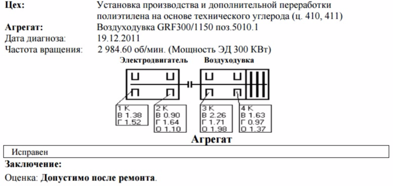
Fig. 9. Photo of the supporting structure of the GRF300 / 1150 5010.1 blower after repair.
Example 4.
4.1 Inspection of the unit was carried out according to the schedule after repair.
Fragment of the diagnostic protocol
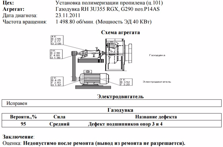
Comments:
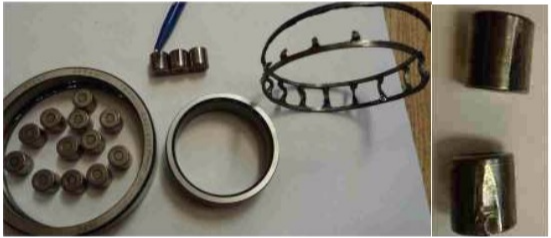
The RMS level of vibration acceleration of bearings of bearings 3 and 4 is 101.23 m / s² and 95.72 m / s², which indicates increased friction in the bearing units, see Fig. 10.
After repair from 10.26.2011 RMS spectrum of vibration acceleration 10 000 Hz, see Fig. 11.
After repair from 07.20.2011 a similar situation was observed, see Fig. 12, as a result, the bearings lasted less than a month.
Fig. 10. Vibration acceleration spectrum of 10 000 Hz of support 3 of 11.23.2011.
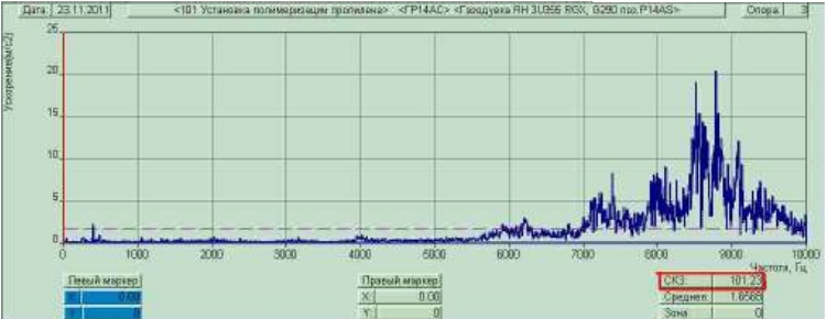
Fig. 11. Vibration acceleration spectrum of 10 000 Hz of support 4 from 10.26.2011.
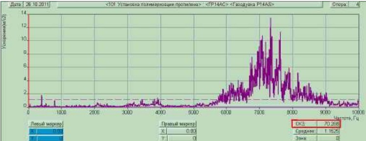
Fig. 12. Vibration acceleration spectrum of 10 000 Hz of support 4 from 07.20.2011.
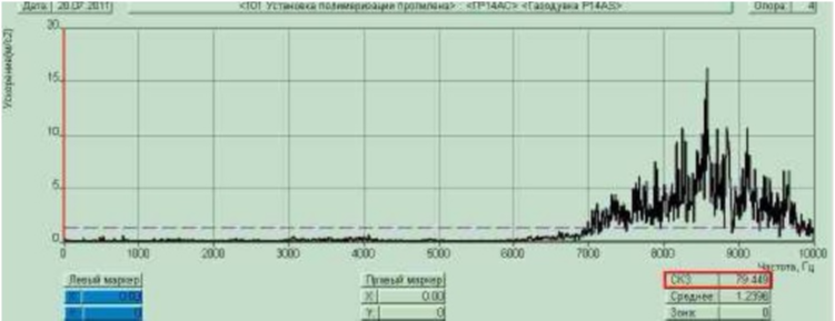
Fig. 13. Photo of the dismantled bearing support 3.
4.2 The state of the unit after additional measures initiated by the vibration diagnostics group.
Fragment of the diagnostic protocol
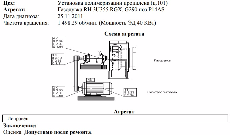
Example 5.
5.1 Inspection was carried out according to the schedule before repair.
Fragment of the diagnostic protocol
Comments:
The main cause of increased vibration is misalignment of the gear train (see Fig. 16).
Fig. 14. Photo Extruder ChPSp 320x10 pos. A-404/1.
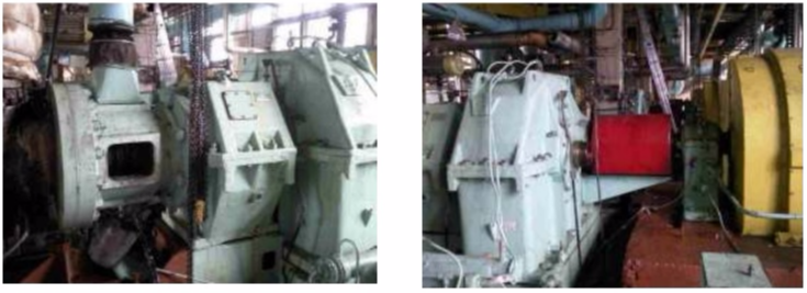
Fig. 15. Direct spectrum of vibration acceleration from 2-1000 Hz. Bearing No. 5, horizontal direction.
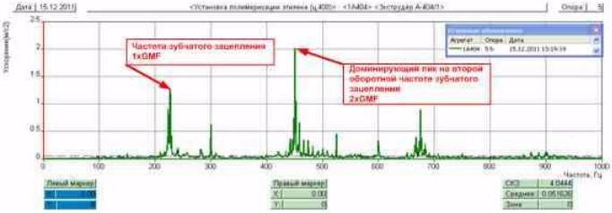
Excitation of the second harmonic of gearing is caused by misalignment of the gearbox shafts. Due to this defect, an increased value of the RMS of the vibration velocity in the axial direction on the support No. 5 is observed.
Recommendations:
1. Ensure instrumentation of level 1 (vibration monitoring of the unit) - at least 1 time per day. With a sharp change in the level of vibration relative to the values of this examination (1.5 times or more, but not less than 1 mm / s), initiate VD (CMVP level 2).
2. During the period of the next scheduled repair: revise the gearing of the gearbox (check the parallel alignment of the gear pair), revise the bearing of bearing No. 5.
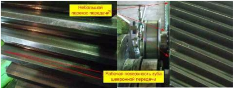
As a result of the revision of the extruder gear pos. A-404/1 revealed a slight bias in the chevron transmission. Since the repair of this defect is lengthy, corrective measures were developed to eliminate the defect during the period of stop repair (inspection and repair of the bearing seats of the gearbox, parallel laying of the shafts and chevron transmission), and periodic monitoring of vibration parameters was organized before the repair.
Fig.16. Photo of a chevron transmission at revision.
Example 6.
6.1 Inspection was carried out according to the schedule after repair; the unit was in continuous idle time; there is no data on the state of the unit before repair.
Fragment of the diagnostic protocol
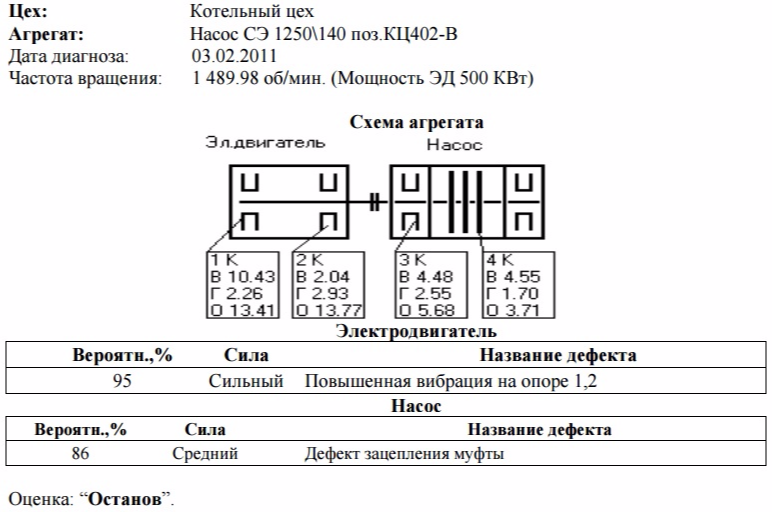
Fig. 17. Photo of the supporting structure of the electric motor of the pump unit SE. Supports 1.2 (rear left foot of the engine, rear right foot of the engine, respectively). Contour diagram of the support 1 of the electric motor Hairpin-Lap-Rama-Mortgage foundation.
Recommendations:
To strengthen the supporting structure of the support No. 1, the revision of the coupling connection.
Comments:
Due to the long technological idle time of the unit, vibration inspection was not carried out before repair, the defect of the supporting system could be determined even earlier. However, the unit after repair did not pass the routine run-in. During 2011 construction and installation work was carried out at this position to replace the frame and foundation.
6.2 Condition of the unit after additional measures initiated by the vibration diagnostics group.
Fragment of the diagnostic protocol
Comments:
The coupling engagement defect is not critical; periodic vibration monitoring of the unit state is required.
Recommendations:
During the next repair or technological shutdown, repair the coupling joint.
Fig. 18. Photo of the supporting structure of the ED pumping unit SE after repair.
Stationary diagnosis system for piston compressors PROGNOST
Brief information about the PROGNOST system:
During vibration testing of rotor-type mechanisms, the “simple” method of monitoring the average vibration level has so far been used.
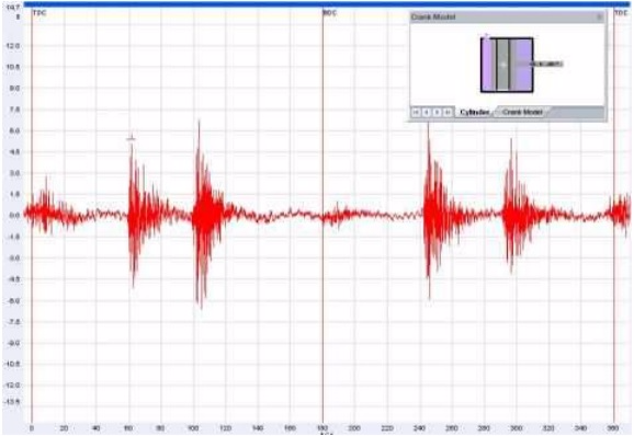
Fig. 19. Acceleration signal (above) and the RMS level of the vibration signal (below) for one crankshaft revolution.
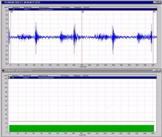
The PROGNOST system provides a segmented vibration analysis, depending on the angle of rotation of the crankshaft.
During each revolution, the temporary representation of the vibration signal is divided into 36 segments, each 10 degrees of crankshaft rotation. Thus, a relationship is established between vibrational events and the angle of rotation of the crankshaft depending on the functioning of the compressor, for example: opening / closing of suction / delivery valves, vibration at the moment of reverse of the movement mechanism, and others. RMS individual values are calculated or absolute maximums for each segment, which are compared with the corresponding individual settings.
Fig. 20. Acceleration signal and RMS values for each of the segments.
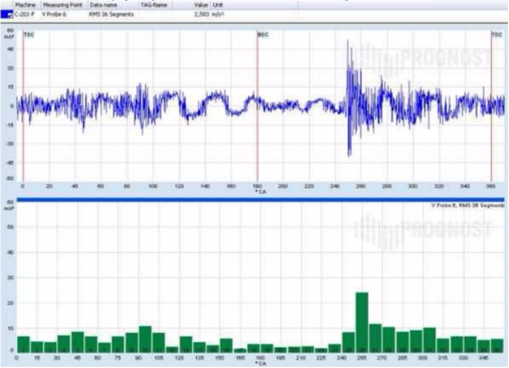
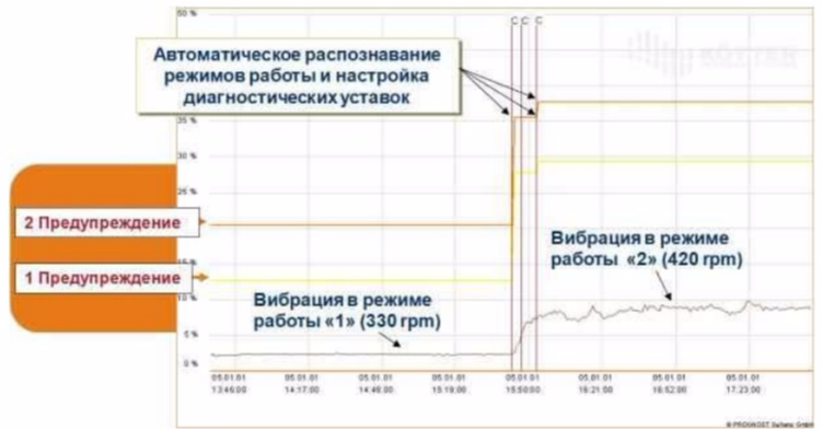
Depending on the technological mode of operation of the piston mechanism, the setting for all segments is individually changed individually for each compressor.
Fig.21. The trend of vibration acceleration and automatic selection of the setpoint depending on the technological mode of the piston mechanism.
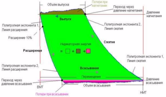
The received and recorded pressure curve is converted into a pressure-volume diagram (Pv diagram), for which the characteristic
values for certain fixed points. Damage to valves, piston rings, and seals resulting in leaks causes changes in characteristic values on the measured pressure curve.
Fig. 22. Analysis of Pv diagrams.
PROGNOST ® systems are not adapted for reciprocating machines, but are specifically designed for monitoring reciprocating machines.
Example 7.
7.1 Inspection of piston compressor 1 of the cascade of Production of polyethylene RT1.4M16-12.5 / 17-281M1 pos. A-124 using the PROGNOST diagnostic system.
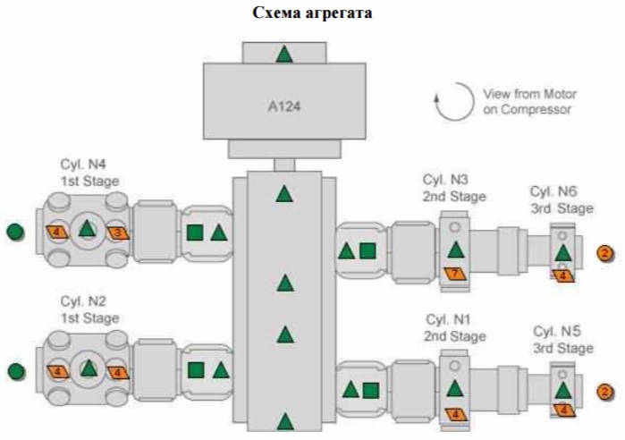
When using a segmented analysis of vibration, vibration acceleration signals using a stationary Prognost system, together with specialists from the New Monitoring Technologies firm, a suction valve was found to malfunction on the side of cylinder cover No. 4.
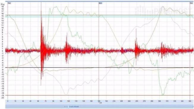
Fig. 23. Signal of vibration acceleration of the 4th cylinder of the piston compressor РТ1.4М16-12,5 / 17-281М1 pos. А-124 (red), signals from pressure sensors from the cylinder head side (brown), from the crankshaft side (green) and piston force stock (purple). Date of examination: 24.01.2012.
During the repair period, it was recommended to replace the suction valve of cylinder No. 4 on the cylinder head side.
Fig. 24. The signal of vibration acceleration of cylinder 4 of the piston compressor RT1.4M16-12.5 / 17-281M1 pos.A-124 on 02.15.2012. After the repair.
During the repair, the valve was replaced, as a result, the vibration decreased significantly (1.5 times).
Fig. 25. 3D Spectrum of the amplitude of vibration acceleration of the 4th cylinder of the piston compressor RT1.4M16-12.5 / 17-281M1 pos. A-124.
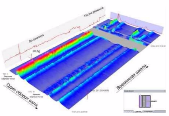
When the valve was opened, a fragment of material was found in the groove under the valve plate, from which the cylinder rings were made. When the compressor was operating during the valve opening, the chip caused vibration when gas passed through the valve. It turned out that the valve was working, but could fail when grinding the debris material and falling under the valve plate. In addition, according to the presence of a fragment, it can be assumed that one of the rings of the specified cylinder requires replacement during the next repair.
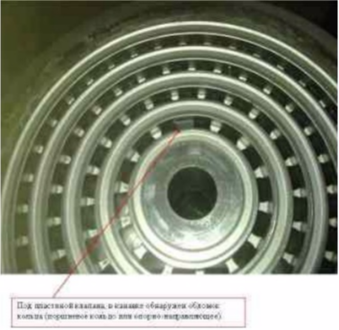
Fig. 26. Photo of the suction valve of the 4th cylinder of the piston compressor RT1.4M16-12.5 / 17-281M1 pos. A-124.
Conclusion
General statistics of the vibration diagnostics group for the period from June 2010 to December 2011 (19 months).
Vibrodiagnostics of the units at the first stages of the transition to the repair system “according to the technical condition”, basically, already made it possible to determine the actual technical condition of the units, find the problem areas of the equipment, and accumulate a database of the vibration state of the equipment. Vibration tests allow timely take measures to equipment with critical estimates based on the results of vibration diagnostics, as well as to allow an increase in the overhaul intervals in the absence of defects in the equipment and during organized periodic vibration monitoring and vibration diagnostics.
The Tomsk experience of vibration diagnostics, the qualifications of our specialists and the well-established work of the enterprise’s diagnostic service confirm the reality of Tomskneftekhim’s plans to switch to technical maintenance and repair of equipment in technical condition, together with reliable partners of PromService, NTM and Prognost. But much still needs to be done for this: to gain experience, to be equipped with backup equipment, to obtain a formally agreed right to such a transition.