Technical diagnostics of pipeline industrial valves with electric drives at nuclear power plants
Currently, the diagnostics of pipeline valves is widely developing at nuclear power plants and there is reason to believe that this type of diagnosis will conquer many other industries. Smolenskatomtekhenergo specialists will tell you what the diagnostics of electric actuator fittings are.
Introduction
The technical diagnosis of industrial pipeline valves with an electric drive, as the most common at NPPs (compared to hydraulic, pneumatic, and electromagnetic drives), is of practical interest due to its significant impact on the safety of NPPs and the relatively high cost of repairing them.
So, for example, on one RBMK-1000 NPP unit, about 3,500 units of electric valves are used.
The tasks of technical diagnosis of electric valves are:
- determination of the type of its technical condition;
- finding a place and determining the causes of failures or malfunctions;
- forecasting the technical condition for a given time interval.
Of particular interest is the technical diagnosis of pipeline valves with electric drive at the stage of commissioning of nuclear power plants (within the framework of the project "AES-2006").
At the stage of commissioning (at the input and post-installation control), it is necessary to diagnose the valves with registration of its initial parameters to create a database in the automated process control system. This database will be the main one for assessing the operational state of valves and its individual components.
The choice of diagnostic method
The depth of search for the place of valve failure (malfunction) depends on the selected diagnostic parameters, which are determined by the design and operating conditions, as well as the suitability of the valve for diagnosis (suitability).
When diagnosing, the requirement must be fulfilled - the lack of refinement (changes in the design) of the valve and electric drive.
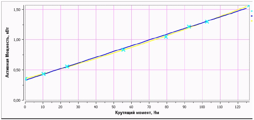
The main diagnostic parameters of the electric drive are the torque on the output shaft and the active power of the electric motor. The dependence of the active power of the electric motor on the torque on the output shaft is confirmed by experimental data.
In general terms, such a dependence (calibration dependence) can be represented in the form of a graph, where:
along the X axis - the torque value on the output shaft of the electric drive (N · m),
along the Y axis, the values of the active power of the electric motor of the electric drive (kW).
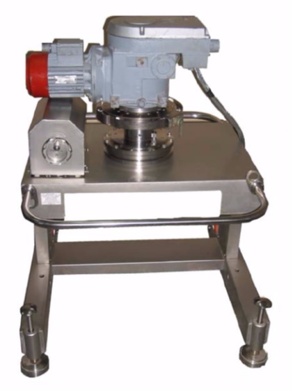
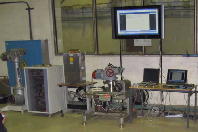
At the first stage of diagnosis, the electric drive is calibrated at the points of monitoring the technical condition of the electric drives or at the place of installation of the electric drive. In this case, test actions are performed (setting the braking torque on the output shaft of the electric drive) on the "Bear-04" setting and measuring torque devices (Smolenskatomtekhenergo) or similar:
- to check the values of the minimum and maximum torques developed by the electric drive;
- to check the tuning range and build a schedule for regulating the limiters of the greatest moment of electric drive "torque switches";
- for registration and construction of a calibration dependence - torque from active power
where:
P, kW - is the active power of the drive motor;
M, N · m - torque on the output shaft of the drive;
- to configure the limiters of the greatest moment of the electric drive "torque switches" in accordance with the technical specifications for valves;
- to check the operability of the electric valves of systems that are important for safety when deviating the parameters of the supply network (voltage, frequency) from the nominal values.
At the second stage, valves are tested at the installation site. At the same time, in the valve’s actuation cycle, the active power, voltage, current, discrete signals from the limit and moment switches are measured and recorded using external means - the Sprut-7 module (Smolenskattekhenergo) or similar, or using built-in means - such as SIPLUG ( AREVA NP).
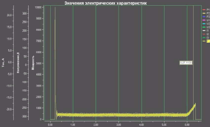
Based on the drive calibration data, the following is calculated:
- torque at characteristic points of the valve cycle (idling, blasting, sealing, etc.) - the main diagnostic parameter of the valve;
- time characteristics (tripping, tripping delay, cocking time of limit and moment switches, etc.).
The frequency of diagnosis
The frequency of diagnosis depends on the degree of influence of the valve on safety.
In accordance with "RD EO 0648-2005. Regulation on the technical diagnosis of electric pipeline industrial valves at power units of Rosenergoatom Concern", the methodology for determining the categories of AC electric valves is based on a point assessment of the factors determining the priority of technical diagnostics.
In this case, scores are used that take into account:
- classification of fittings;
- type of reinforcement;
- the influence of the temperature of the working environment;
- the influence of the speed of the working environment;
- the number of valve response cycles per year;
- the influence of subjective factors based on operating experience.
Technical diagnostics using external means should be carried out:
- for electric actuators of category 1 - 1 time per year;
- 2 categories - 1 time in 2 years;
- 3 categories - 1 time in 5 years;
- after repair of fittings of categories 1 and 2.
Express Diagnostic Tools
In practice, internal and external means of technical diagnostics of valves with an electric drive are used. Of particular interest are the means of rapid diagnosis of electric valves (built-in).
When using the built-in means of express-diagnostics of valves with an electric drive, automatic registration of electrical parameters occurs when the valves are triggered (without the participation of operating personnel when the unit is operating at power) and the parameters are entered into the ACS TP database. This occurs more often than the established frequency.
Diagnostic steps
Stages of technical diagnostics of reinforcement of nuclear power plants and its application in ACS TP AC:
- initial diagnostics of valves (at the stage of commissioning with input and post-installation control) using external (portable) diagnostic tools (for example, production of Smolenskattekhenergo or similar) and creating a database in the automated process control system;
- automatic registration of parameters when the valves are triggered (without the participation of operating personnel when the unit is operating at power) using stationary (built-in) diagnostic tools and entering parameters into the ACS TP database;
- automated control of the operational state of the reinforcement and its individual units by comparing the current values of the parameters in the ACS TP database with the initial and calculated ones.
The speed of analysis and diagnosis (rapid assessment of the current technical condition) of the valves in the automatic process control system will allow to identify and timely eliminate violations in its operation.
The data accumulated during operation (operation history) will allow predicting the technical condition of pipeline valves for the coming period and applying the maintenance and repair strategy for the technical condition.
Foreign experience in using built-in technical diagnostics
On some nuclear power plants in the USA and Germany, built-in technical diagnostics (operational diagnostics) are used. They are designed for automatic registration of parameters when valves are triggered (without the participation of operating personnel when the unit is operating at power). For example, in Germany, the SIPLUG family (company AREVA NP) is used, previously the MCC (Motor Control Center) system for recording electrical parameters - current, active power of the drive electric motor.
The latest generation of SIPLUG Online 3 devices has been designed for a distribution cabinet (low-voltage switchgear enclosure).
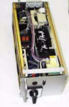
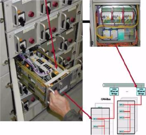
Here, the diagnostic components are rigidly integrated into the retractable module and brought out through a plug connection for networking.
If the drive is set in motion, the measurement is automatically recorded.
At the end of the measurements, the record is transmitted through the network and made available for further processing to all workstations.
The development of diagnosis in Russia
Automated process control systems for new projects of nuclear power units should be equipped with means for continuous collection and analysis of diagnostic information on the state of valves during operation.
It seems appropriate in the framework of the project "NPP-2006" for valves of systems important to safety:
- to establish the production of blocks for technical diagnostics of valves (type SIPLUG 3 On-line) using in ACS and ACS TP AC;
- carry out pilot work for the Rostov-2 nuclear power plant (in the amount of 15-20 pcs of the most critical valves).
Authors: A.V. Serdyuk, E.I. Friedberg "Smolenskatomtekhenergo"