The Five Conditions
Vibration diagnostics can not always accurately indicate the root cause of the poor technical condition of the equipment. There are various defects that can occur at the same frequencies. Therefore, before doing a more in-depth analysis, Victor Wowk, based on his experience, suggests using simple tools and methods to check the five conditions that will help identify the most common equipment problems. It is recommended that you keep this knowledge in your arsenal and apply it to novice mechanical engineers.

Vibration analysis of machinery has proven useful to identify problems and improve reliability. It is no longer an infant technology, but is not mature enough to diagnose conditions with certainty. Senior diagnosticians still rely on proven age-old techniques to work through those difficult situations. When approaching a serious machine problem, it is useful to keep in mind the fundamentals and step through them in the diagnostic journey. The five conditions described in this article are necessary for any machine system to operate well. They are not the complete story, because some pre-existing conditions must also be satisfied, such as good lubrication, tight hardware, good bearings, and no serious cracks. If these preexisting conditions are known to be good, then the five conditions in this article should be investigated for before delving into other possible causes. With a few exceptions,
machine systems (driver, driven, speed changer, and accessories) can be setup to startup well and restored to smooth operation with a few simple tools and established procedures. Every young mechanic and new engineer responsible for machinery is advised to keep these basics in their toolbox and apply them before investing time and resources into more sophisticated analysis paths.
For any rotating system to operate smoothly and without premature failure, there are only five simple conditions that need to be satisfied. They are: straight shafts, aligned bearings, mass balanced, shaft alignment, and free from resonances. This might sound too simple to be true, but a lifetime of fixing vibration problems on machinery has led me to one of these five general categories. The lifetime I speak of is actually about 30 years, because I was not doing vibration analysis on machinery as an adolescent or while serving in the Department of Defense.
The source of all machine vibration is less-than-perfect manufacturing or less-than-perfect repair. It is possible that bearings can be worn, hardware is loose, parts are dirty, or there is insufficient lubrication. These other conditions are usually not present on new or recently repaired machines, so I will assume that these have already been checked. The assumptions are that the bearings are good, all hardware that needs to be tight is tight, parts are clean, there are no serious cracks and everything is well lubricated. This is the scenario that describes my entry into serious vibration or failures. The obvious has already been checked and corrected.
The procedure for diagnosing machine vibration or failures starts with a vibration analysis, but vibration analysis cannot diagnose anything with certainty. It can only direct further diagnosis by narrowing the list of possibilities. An obvious example is unbalance, which is the easiest thing in the world to diagnose, but other defects such as bowed rotors, misaligned bearings, eccentricities, and misaligned shafts can produce identical symptoms.
Vibration analysis is also plagued with measurement anomalies (phantoms, modulation, electromagnetic noise, and self-generated signals), and errors in interpretation. Diagnosing machine vibration or failures, with confidence, boils down to testing for these five conditions and an uncomplicated process of elimination. The tests for these conditions are relatively straightforward.
Straight Shafts
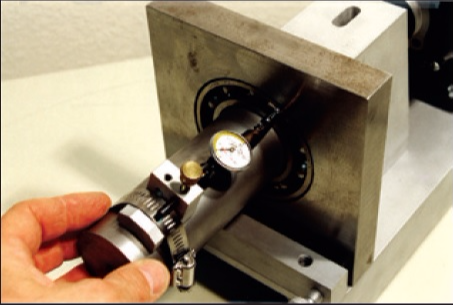
A dial indicator fixed with a magnetic base is the instrument of choice here. A machined shaft should have a total indicator reading (TIR) of no more than 0.001 inch (0.025 mm). This includes all motor and pump shafts anywhere and everywhere along their entire lengths. Fan shafts should meet this criteria on every precision-machined part of the shaft, especially at the journals where the bearings fit.
I might accept slow-speed shafts up to 0.002 inch TIR (0.05 mm). Between 0.002 inch to 0.005 inch (0.05 - 0.127 mm), the rotor will be difficult to balance, and the bearings will get beaten up. Above 0.010 inch (0.25 mm), the rotor cannot be balanced.
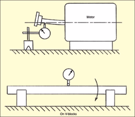
This run-out measurement can be done in situ with the rotor supported in its own bearings, or it can be done on a bench with the shaft supported in V-blocks (wooden or plastic). Figure 1 shows this measurement.
Aligned Bearings
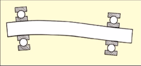
The two bearings that support the shaft (all the bearings if there are more than two) must be coaxial with minimum offset and minimum angularity. Small deviations can be accommodated by the clearance in the bearings. Once the bearing clearance is fully consumed, then a hard stop is encountered with metal pressing against metal. The shaft then deflects and is no longer straight and the bearings suffer a beating (Figure 2).
The need for precise bearing alignment is well understood by machine-tool builders. They control it by line-boring housings, using arbors and fixtures for maintaining alignment during assembly in a clean environment using heat or cold, or a combination of these, to allow insertion without galling metal. In the field, alignment is less controlled during bearing replacements. There is also the variable of non-flat foundations on site, which can distort machine housings and seriously disturb the bearing alignment. The foundation does not necessarily have to be flat. It only needs to be a good match to the bottom of the machine feet so that strain is not transmitted into the housing. This is the domain of millwrights and the practice of shimming.
Fortunately, there are two simple tests for judging bearing alignment at the machine. The first is to rotate the shaft by hand and see that it spins freely. It should spin with minimal friction and no binding during a 360-degree rotation. The second test requires a dial indicator again. This is used to check the parallelism of the faces and their perpendicularity to the shaft. The two test setups are shown in Figures 3 and 4.
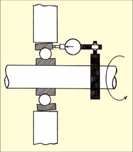
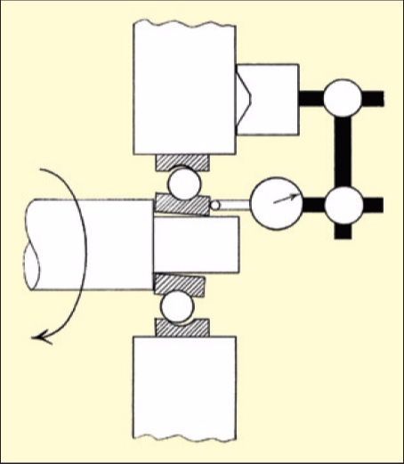
Figure 3 checks that the face of the outer ring is perpendicular to the shaft axis. The indicator is fixed to the shaft with a clamp, and the indicator tip reads on the face of the outer ring as the shaft is rotated. The total indicator run-out should be no more than 1.0 mil per inch of swing diameter.
Figure 4 checks that the face of the inner ring is not crooked on the shaft or that the shaft is not bent. The dial indicator is affixed to the housing or a stationary part, and the tip of the indicator reads on the face of the inner ring as the shaft is rotated. The acceptable reading is again no more than 1.0 mil per inch of swing diameter TIR.
These dial-indicator measurements are not always possible if the rings are not accessible, but if they can be done, then adjustments with a punch and hammer, shimming, or repositioning pillow blocks can be done in place while observing the dial indicator. Aligned bearing operation is cool and quiet, and they have a normal life.
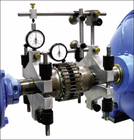
This bearing alignment issue is serious and usually introduced during bearing repair. The tests in Figures 3 and 4 are almost never done by mechanics, even though they are described in the Machinery’s Handbook, first published in 1914. This is a lost art in the maintenance field. Figure 5 is a photograph of this test being done using a universal test indicator.
A serious condition of bearing misalignment can be introduced during operation as things heat up. The thermal expansion forces have the capability to bend the shaft and distort the housing or the frame. Thermal expansion can be measured, but it is most often calculated and predicted. We can do nothing to stop thermal expansion. The best we can hope for is to accommodate for it by providing some room for metal to grow into. This is an engineering function for the machine designer, but the mechanic must be aware of this because he or she will be the last person with their hands on the machine, and when problems arise on start up, fingers will point in their direction.
Floating, or expansion, bearings provide this clearance for thermal growth, and their proper setup is part of bearing alignment. If not properly done, then the machine may start OK when cold, but vibration and noise will worsen as temperatures rise. This is the key indicator to stop the machine before it is too late.
A straight shaft with aligned bearings will not only rotate freely by hand, but it will also balance well.
Mass Balanced
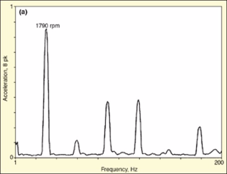
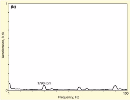
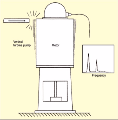
Unbalance is a common condition causing vibration on rotating machines and mass balancing is a common corrective procedure. The indication for unbalance is obvious – a shaking force. It is easy to diagnose with a vibration instrument that provides frequency information. Unbalance is always a high-amplitude motion exactly at rotating speed (Figure 6). As noted earlier, other defects can cause similar vibration symptoms. This is not uncommon in the vibration analysis business; i.e., for multiple defects to cause similar symptoms or for symptoms to be compounded.
Vibration analysis is not a perfect technology, nor is it mature enough to be called a science. It is still an art, because it requires a healthy dose of judgment and experience in the analysis of the data. The only true diagnosis of unbalance is to place correction weights and see that the vibration is reduced.
Rotors can become unbalanced in service if they accumulate debris unevenly (like dirt, grease, minerals from water evaporation, insect or rodent droppings) or erode away material from an abrasive fluid stream. They can also develop cracks or looseness. Therefore, prior to mass balancing, it is wise to verify that the rotor is clean, has no cracks, and everything is tight.
The vast majority of mass balancing in industrial and commercial environments is on fans, which are sensitive to uneven mass distribution because of their light weight, high speeds, and large diameters. Mass balancing is fun because it provides immediate job satisfaction, but it is a dangerous business. The danger is in test weights coming off, multiple starts and stops, leaving tools or other parts in the rotor cabinet, and damaging the machine with too large or improperly placed weights.
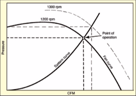
Poor system matching to the resistance in the pipes, ducts, downstream devices, and poor inlet flow conditions can create choking, surging, or stalling. This can produce vibrations that look like unbalance. Therefore, prior to mass balancing fans or any other flow machine, it is wise to verify that they are operating on a good part of their curve, which is the best operating point to the right of the peak (Figure 7). This is even more important for blowers and
compressors that operate at higher pressures and on pumps that handle higher-density fluids.
Shaft Alignment
The only true way to diagnose shaft misalignment is to stop the machine, attach a measuring fixture, and swing readings (see Figure 8). It is not possible to diagnose poor shaft alignment from vibration readings alone, because bowed rotors and misaligned bearings produce identical vibration symptoms as misaligned shafts. In fact, all three are similar physical conditions at the bearings and generate the same kind of wear. However, it is possible to prove good shaft alignment with low vibration, and this also proves a straight shaft and aligned bearings.
The type of coupling is a major factor that determines how much forces are transmitted to the bearings from misaligned shafts. Obviously, more flexible and larger-clearance couplings can accommodate greater misalignments with speed and torque penalties. There is an abundance of coupling choices available today, and the maintenance engineer is free to substitute as long as the speed and torque-handling capabilities are satisfied, with the one exception of torsional resonances. The torsional natural frequency of a rotating system is adjusted by the system designer when choosing a specific coupling. The type of coupling should not be changed on systems subject to torsional pulses, that is, reciprocating machines.
The axial spacing, set as the coupling is assembled onto the shafts, allows for thrust forces, motor magnetic centers, and sometimes thermal expansion. This axial positioning is the responsibility of the one who adjusts the shaft alignment and adjusts the coupling. Coupling spacing is part of the shaft alignment task and is done with micrometers, calipers, thickness gauges, and sometimes dial indicators.
Free from Resonances
This is an easy thing to detect with a quick and simple impact test (see Figure 9). I wish every startup engineer and technician would do this test routinely and put me out of a job. The responsibility for designing machines to have natural frequencies 20% away from operating speed rests with the machine designers, but honestly, they do not have adequate analytical tools to accurately predict this, especially on large machines where the foundation
is provided by someone else.
The most economical way to deal with this state of affairs is to test for it on site and finish the design on site with strategically placed stiffeners. Other fixes are to change speed, add damping, or dynamic absorbers.
Machines and structures have an aging effect where the joints soften over time. This means that natural frequencies go down. A machine may have started its service life with a stiff support structure and low vibration, but as it ages, vibration or bearing wear problems could emerge. This is a subtle effect over a long time that may not be recognized as a resonance. This is akin to an old man’s joints that can’t take it anymore.
A related issue is isolation. Spring or rubber isolation is not a corrective method for machine vibration. It only serves to limit the force transmission or to contain the dynamic vibrations in areas or on platforms. Proper isolation operates on the theory of resonance and on the assumption of infinitely stiff foundation below the springs. When the foundation is not infinitely stiff, or if it changes over time, then machine vibration can change or unexplained failures can emerge. The key test for this condition is an impact test to measure the natural frequency of the machine on its support system to determine if resonance is an active player.
Lubrication
Lubrication is not listed as one of the five conditions, but it is certainly necessary for smooth operation. The reason for discussing it here is that “lack of lubrication” is too often blamed as the cause of failure without sufficient evidence to support it. Sufficient lubrication is one of those easily understood preconditions, like good bearings, clean rotor, and tight hardware. These conditions are assumed to be satisfied before drawing on outside sources to work a machine vibration problem.
The key indicator for lack of lubrication is temperature. This could be during operation, or postmortem, with discoloration, carburized oil, or softened metal. If no evidence of excessive friction, via temperature indicators, is present, then lack of lubrication can be dismissed, along with his big brother of an excuse – “bad bearings”.
The good news is that four of the five conditions, with the one exception being mass balancing, can be evaluated with the machine stopped. So you see, even before the machine is energized, I can measure a few things with dial indicators and an impact test and predict with reasonable confidence how it will behave with balancing. The final diagnosis of balance condition must necessarily be done while spinning. But if the other four conditions are satisfactory,
then mass balancing should converge quickly to a fine level.
So machines are not so complicated that their conduct cannot be demystified with a few simple tests.
Author: Victor Wowk, founder and president of Machine Dynamics, Inc., is a licensed professional engineer.
Тоесть на данный момент проверка посадки внутреннего и наружного кольца подшипника проверяется исключительно универсальным индикатором? А при отсутствии доступа как поступить?
При отсутствии доступа уже никак не проверить. Во всяком случае я таких способов не знаю. Если есть признаки неправильной посадки подшипников по спектрам вибрации и другие возможные дефекты исключены, возможно имеет смысл их демонтировать и смонтировать заново по всем правилам. При этом не будет лишним выполнить осмотр посадочных поверхностей.
А можно вообще разобрать подшипник и посмотреть на дорожки от тел качения. По ним можно точно определить наличие перекосов колец.