Influence of induced vibration on fan bearings
Дефекты подшипников, Вибродиагностика
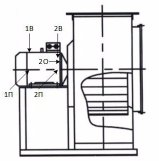
Another interesting example from practice. Two centrifugal fans of 3000 rpm are installed side by side, conventional air filters are at the inlets, the pressure pipe is common, the pressure pipes are rigidly connected to the cochlear flange. One is always at work, the second is in reserve. Switching once a month.
Measure the vibration of fan No. 1 (RMS vibration speed in the range of 10-1000 Hz):
The tolerance according to GOST 31350 is 4.5 mm / s, vibration is normal. But this, as you might guess, is not all. The spectra of the envelope of the vibration signal are not empty, in addition, in a very noisy room, a little extraneous noise comes from the engine. We bring our ear closer and the noise becomes very loud, and this is already interesting. We remove the time signal vibration acceleration:
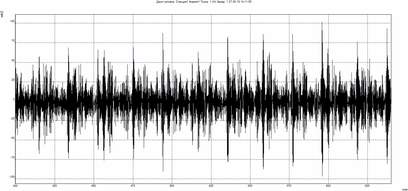
Shock pulses are visible, reaching up to 200 m / s² (!) in magnitude. There is no clear periodicity, which indicates several defects. For the sake of interest, we look at the spectra of vibration acceleration (RMS vibration acceleration in the range of 100-10000 Hz):
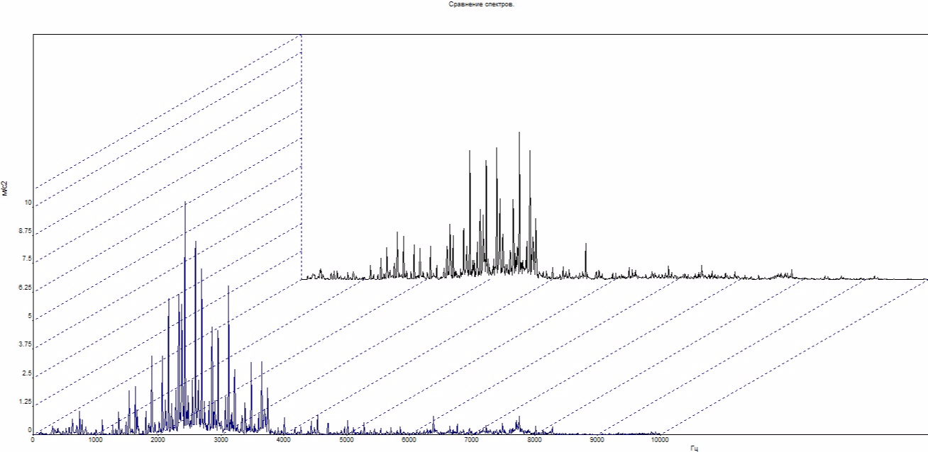
It is not difficult to guess that the defects are very developed and are approaching the last stage of bearing destruction, the RMS of vibration acceleration reaches 30 m / s².
Determine the defect itself. For this we need direct spectra and envelope spectra.
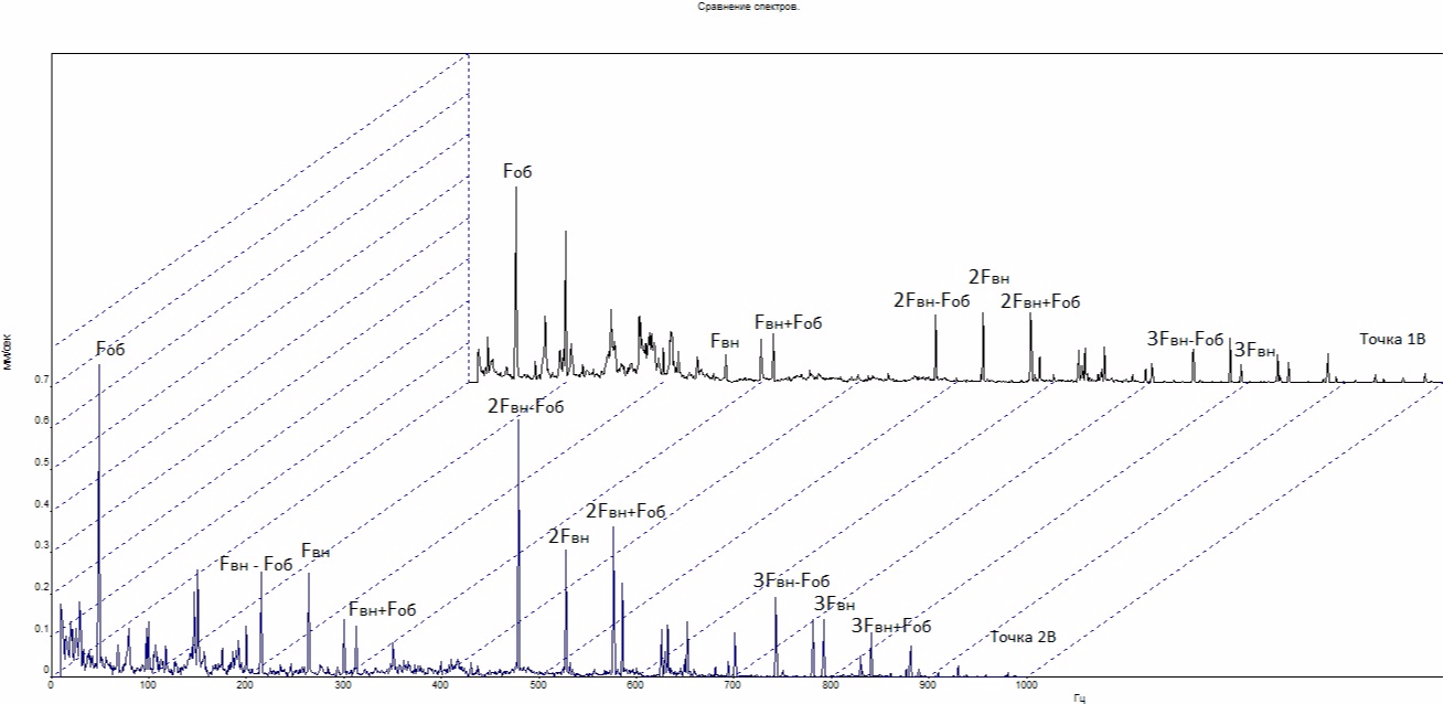
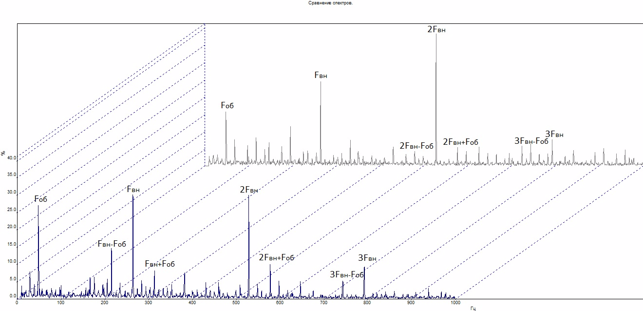
The main components are signed on the spectra. Fоб is the rotational frequency of the rotor of the electric motor (48.7 Hz), Fвн is the frequency of rolling of rolling elements along the inner ring (264.4 Hz) of the bearing 6205 2RS. Difference frequencies Fвн ± Fоб indicate a defect such as shells (chips) on the inner ring of the bearing. When a defective place passes, the rotor decelerates; when it leaves a defective place, it accelerates. You can also see a forest of small amplitude components related to the speed of the separator, which indicates the granularity of the raceways (similarly with the rotor, the separator slows down and accelerates).
I recommend switching to the backup fan No. 2 and taking measurements on it. The spectra are similar and it makes no sense to bring them, only the RMS of vibration acceleration is an order of magnitude lower - up to 3.5 m / s², there is no extraneous noise and the frequencies of the outer ring are also clearly distinguishable.
A protocol is drawn up indicating the presence of developed defects in the inner ring of the bearing and the recommendation of replacing both bearings of fan No. 1 (it is not possible to identify a problem bearing one or both), tracking the development of defects in bearings on fan No. 2 and replacing them with the nearest repair. Fan No. 1 is taken out for repair.
And now to the topic of the post title. We take away the dismantled bearings from the electricians, twist, twist, disassemble and study. One of the bearings is intact, but the second has interesting defects.
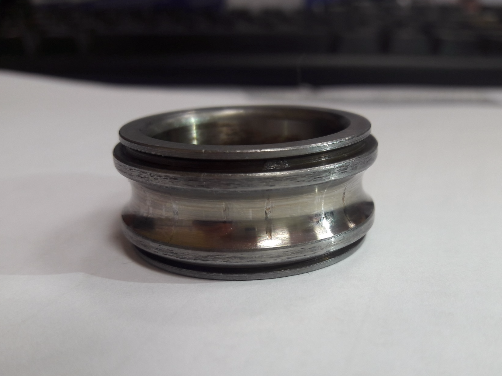
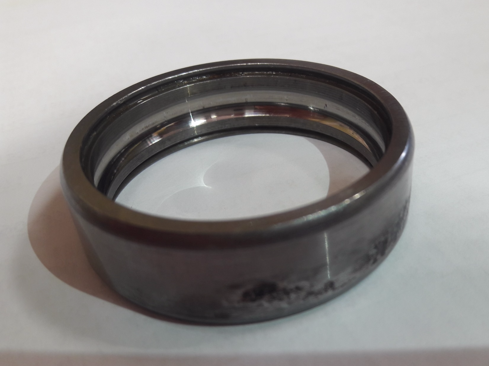
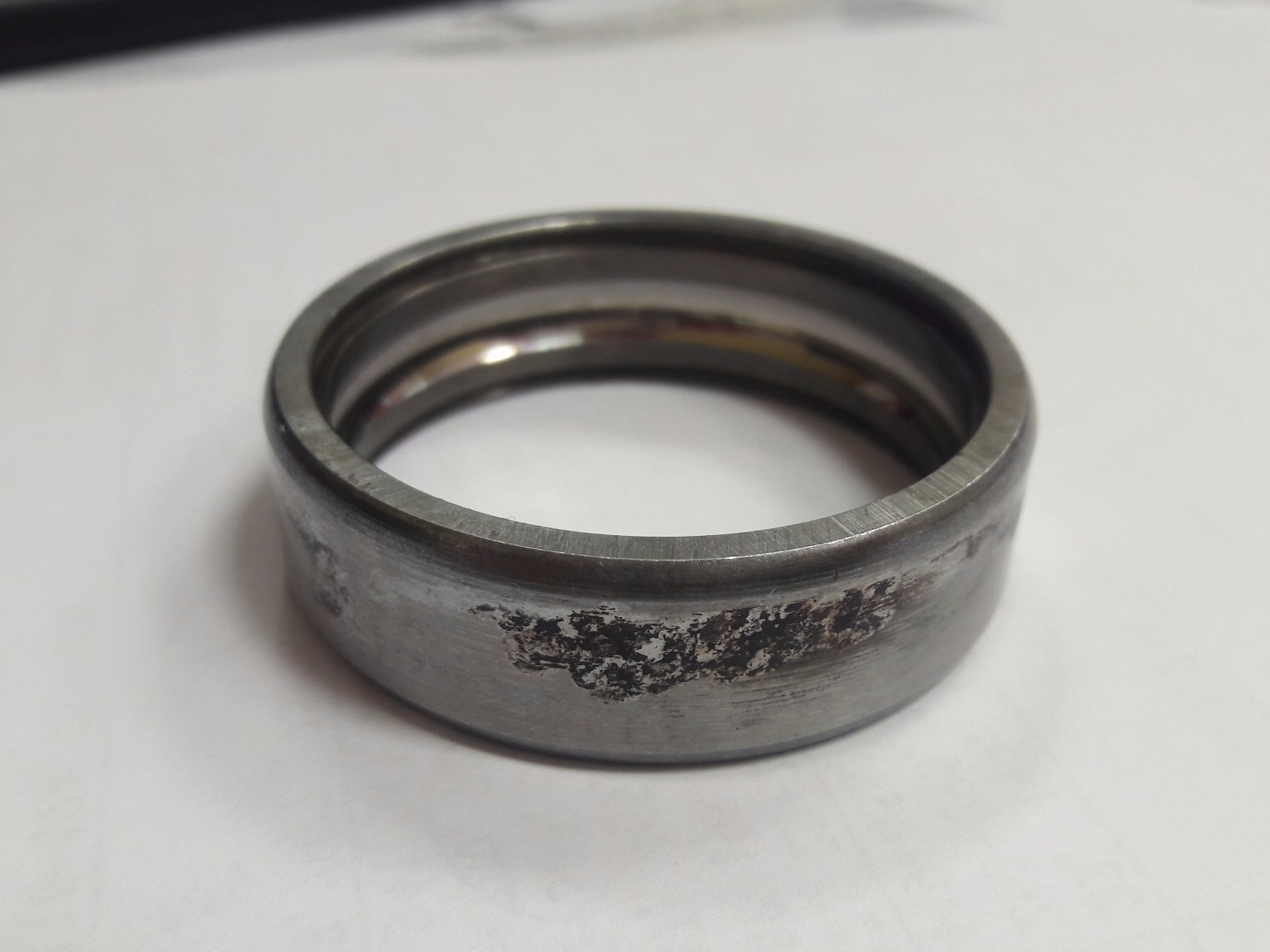
Unilateral damage to the track of the outer ring and false brinelling (elongated dents due to axial movement) indicate that the defect was formed during idle time of the unit under vibration load.
Fretting corrosion (micromotion with oxidation of a constantly worn layer) indicates a weakening of the fit of the outer ring in the motor housing, which the repairmen also confirmed.
There is something to do with false brinelling, so it’s interesting to learn about induced vibration on a standing fan No. 2 from fan No. 1 working after a repair (RMS vibration speeds in the range of 10-1000 Hz):
Vibration is great for an idle unit. Vibration on the pressure pipe in the area of the fan flange is from 2.1 to 2.9 mm / s, which proves the presence of induced vibration from a common pipeline. These circumstances are indicated in the next protocol with the recommendation of arranging soft inserts on ventilation units to eliminate the harmful effects of induced vibration on the bearings.