Bearing electric burn
Дефекты подшипников, Вибродиагностика
For another real example, I propose to consider vibration diagnostics of fan bearings. Let's disassemble the bearings and make sure that inspection is a key step in determining the root cause of the failure.
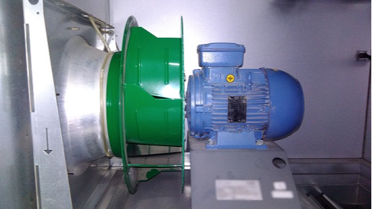
Call to the centrifugal fan of the exhaust system. The reason is strong extraneous noise. The fan motor WEG AL112M-04 (N = 4.0 kW) is powered by a frequency converter.
When turned on with a set of revolutions, the noise from the fan increases and becomes similar to a squeal (very unpleasant). The frequency converter shows 2440 rpm. I define 2308 rpm with a stroboscope. And I do not pay attention to this fact (once again I make such a mistake). We measure vibration.
RMS vibration speed in the range of 5-1000 Hz (n = 2308 rpm):
Tolerance 6.3 mm / s (fan with vibration dampers). After the measurements, it is interesting to listen to the freewheel unit.
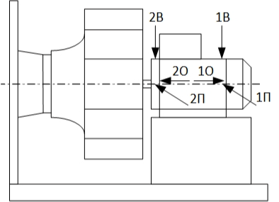
The sound is uniformly noisy, which I found a little odd. After making sure that the impeller does not touch the diffuser, we can safely conclude that the bearings are defective. Next, you need to determine the defects themselves. We will analyze the points 1P (bearing 6206-Z) and 2P (bearing 6307-Z). Since I measure not only vibration but also shock impulses, the analysis will be somewhat extended.
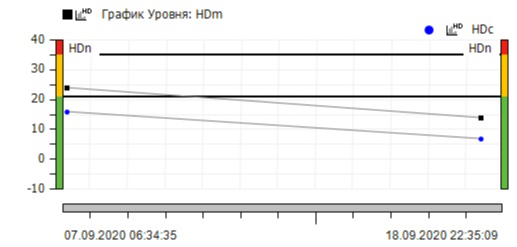
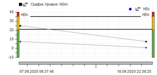
Let's start with shock pulses, more specifically with the SPM HD method. We will not go deeply into theory, but we will dwell on only two main parameters of this method. HDm is a scalar value (measured in decibels) that characterizes the amplitude of the strongest shock pulse and is some criterion for the mechanical state of a bearing. HDc is a scalar value (measured in decibels) that characterizes a certain carpet level (within 200 beats per second). The difference between these two parameters characterizes the quality of the lubricant or the load on the bearing. Empirically determined criteria for the amplitude HDm:
- up to 21 dB green zone (satisfactory condition);
- 21-35 dB yellow zone (there is damage);
- more than 35 dB red zone (critical level).
For bearing # 1 HDm = 24 dB, HDc = 16 dB. For bearing no. 2 HDm = 25 dB, HDc = 8 dB. The delta on both bearings is large, which means a lubrication problem is likely. According to the HDm parameter, both bearings are damaged.
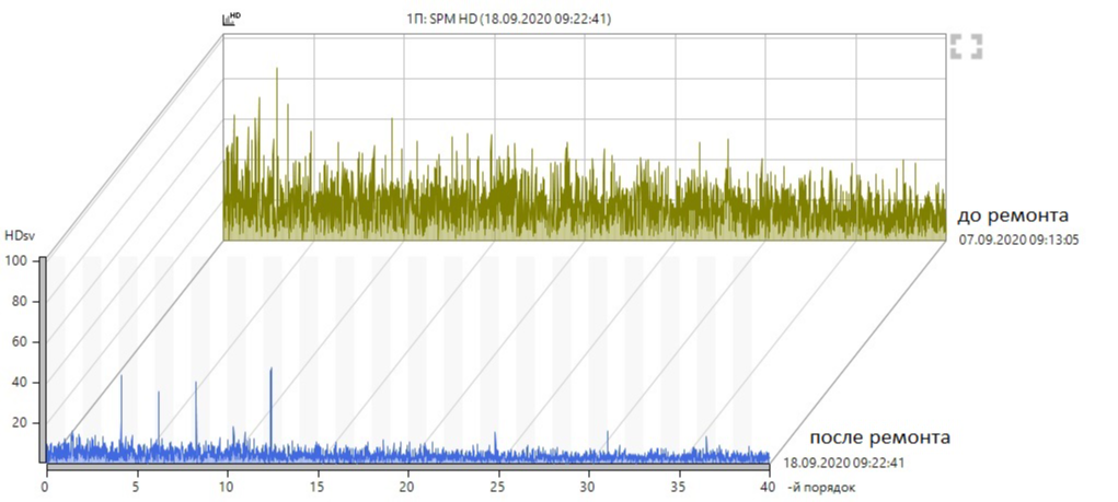
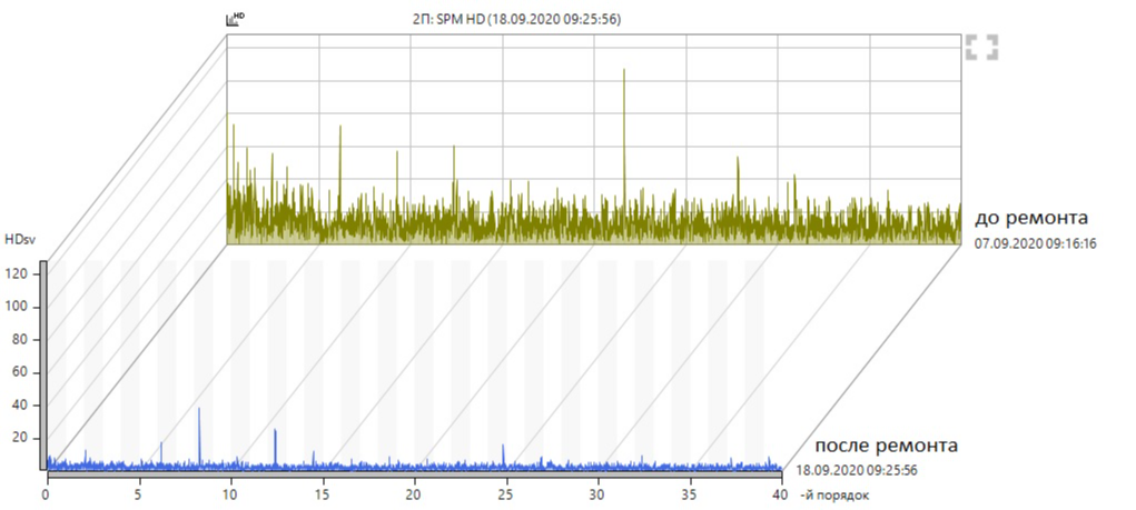
Let us proceed to the analysis of the spectra of shock pulses.
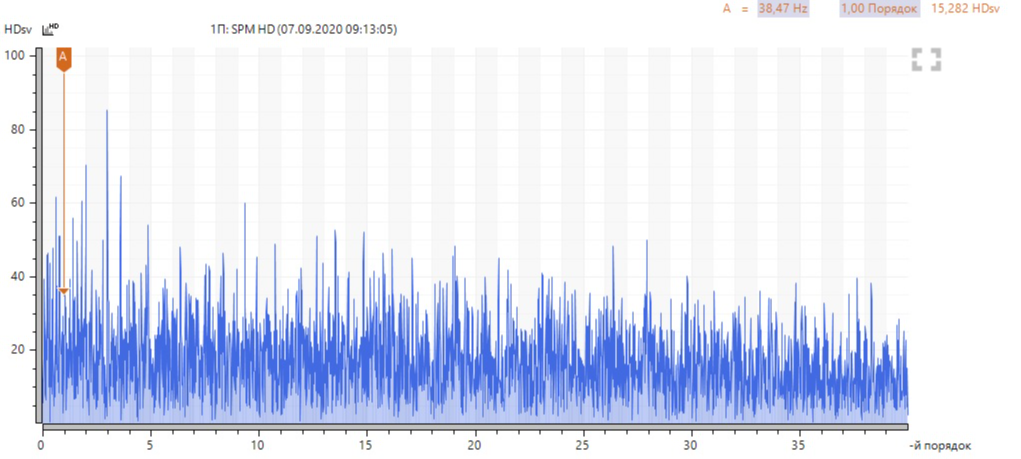
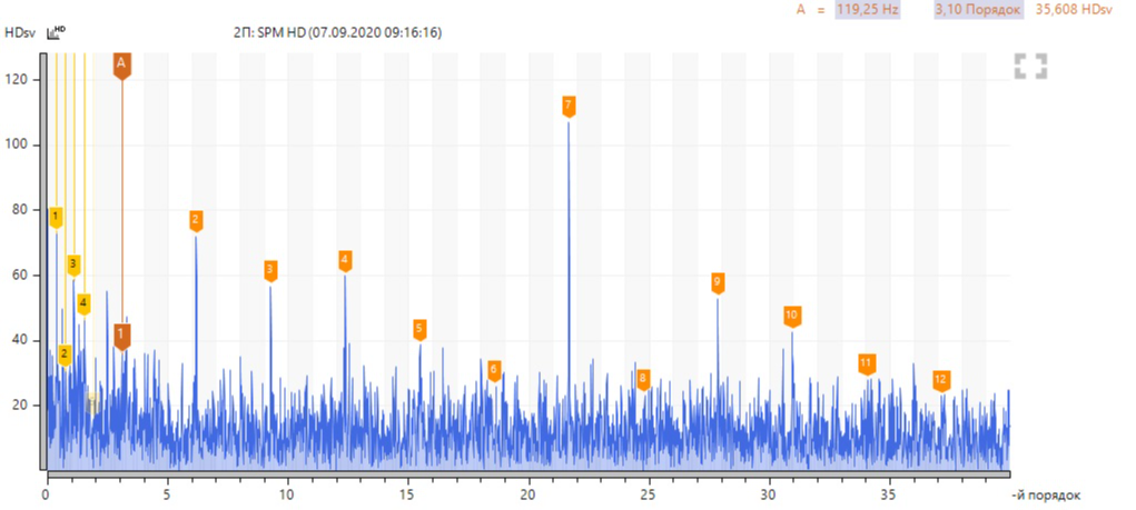
High noise in the spectrum of bearing No. 1 is striking, which is probably due to poor lubrication condition. There are no pronounced frequency components. At bearing No. 2, carpet noise is noticeably lower and there is a harmonic activity of the rolling element rolling frequency on the outer ring (BPFO) of 119 Hz and the cage rotation frequency (FTF) of 14.8 Hz.
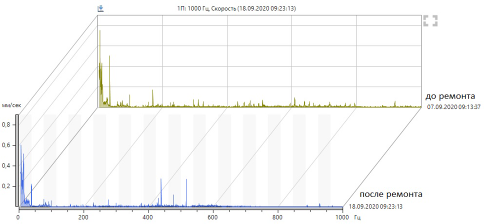
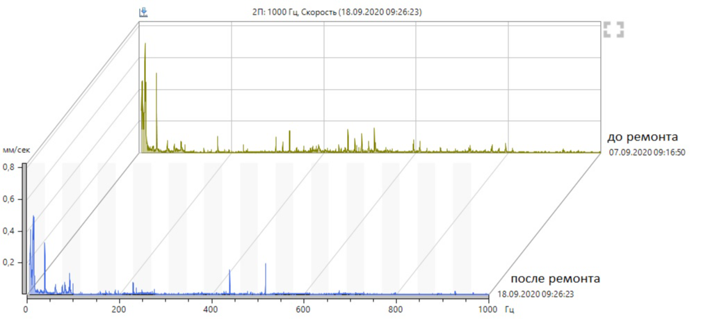
Now let's look at the vibration velocity spectra.
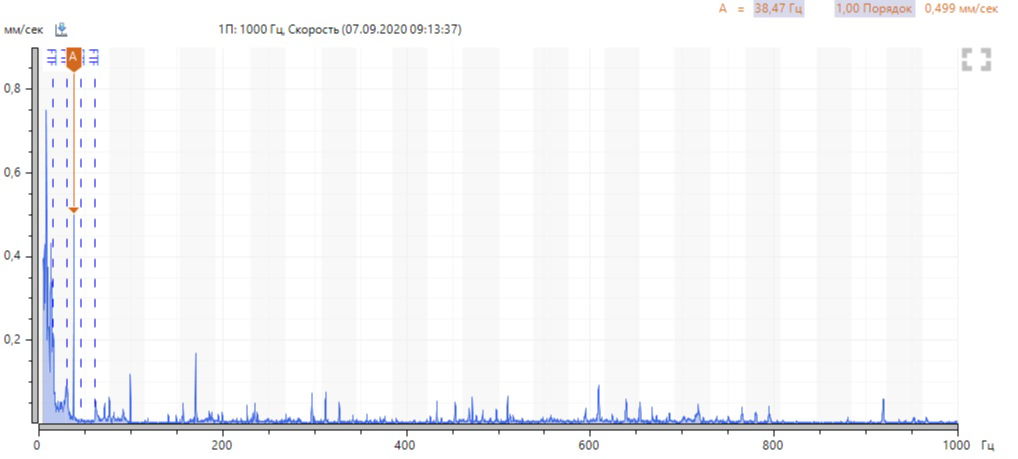
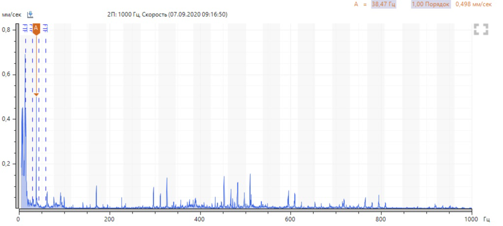
In the spectra, the main energy is concentrated in the frequency range of the separator. In practice, there were similar pictures with the complete destruction of the separator, so I figured that here we have a similar problem.
Consider the envelopes of the vibration signal (HD ENV method).
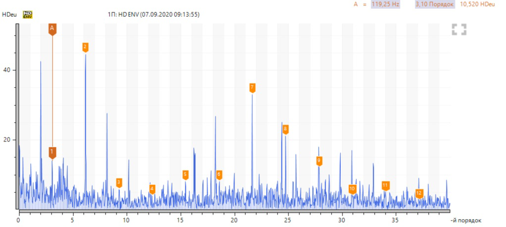
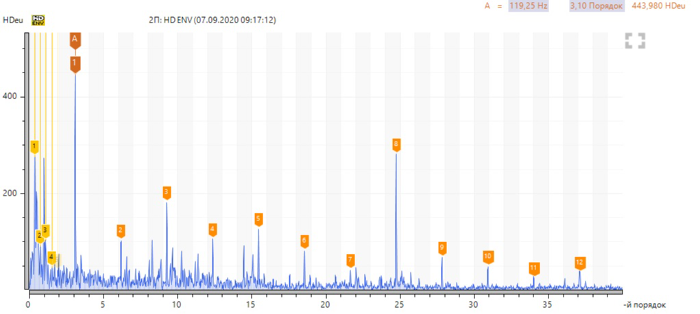
At point 1П, the levels are not high, there are harmonics of the rolling element rolling frequency on the outer ring (BPFO) of bearing No. 2. At point 2П, these components are expected to be more powerful, there is a separator rotation frequency (FTF).
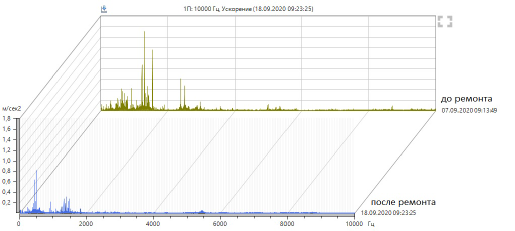
Vibration acceleration at these points is also of interest. At point 1П - 3.9 m / s², at point 2П - 25.6 m / s².
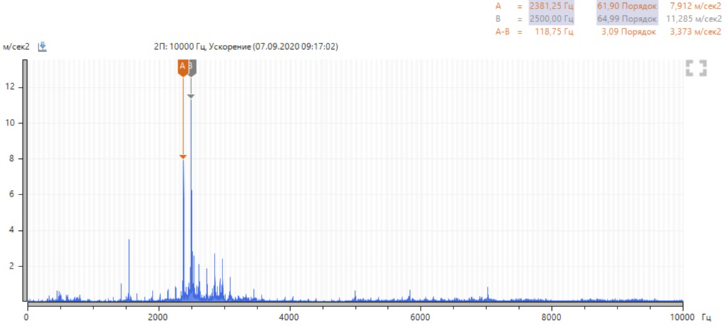
The vibration acceleration spectrum consists mainly of the harmonics of the rolling element rolling frequency on the outer ring (BPFO), especially the 20th and 21st harmonics (marked by markers in the figure above).
I wrote an act on the defect in the outer ring and cage of bearing No. 2, the need to replace it, as well as a recommendation to inspect bearing No. 1. After the repair, they called for vibration measurement, there is no extraneous noise, the rotation frequency on the frequency converter display now corresponds to the real frequency of the electric motor rotor.
RMS vibration speed in the range of 5-1000 Hz (n = 2310 rpm):
Vibration velocity changes are insignificant.
But huge changes have taken place in the high-frequency region.
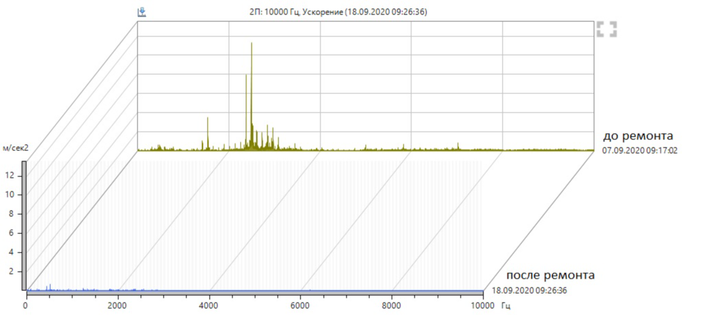
After the measurement, he went to the electricians, who reported that both bearings were replaced. They said that they made it in time - a little more and the electric motor would have burned out. I take the dismantled bearings from them and disassemble them to establish the root cause.
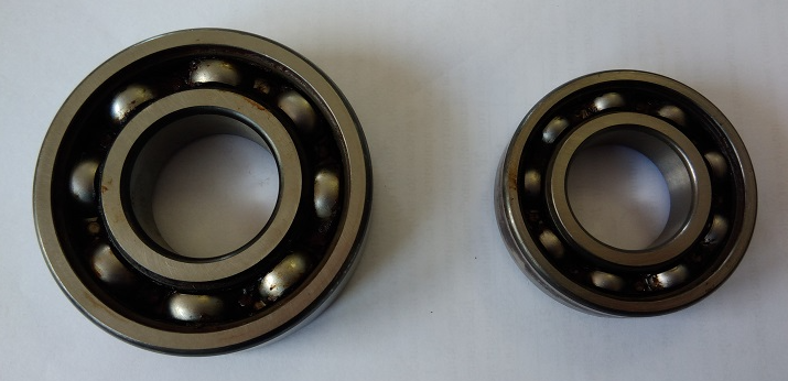
The first thing that catches your eye is that the grease burned out on both bearings.
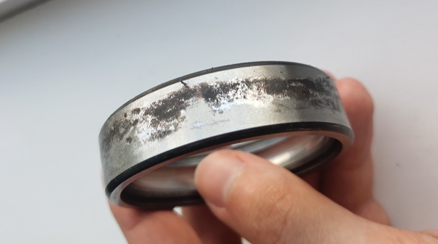
The seating surface of the outer ring of bearing No. 1 is oxidized, which indicates its movement in the electric motor shield (loose fit).
Bearing No. 1 in the cage was almost dry lubricated. Surface wear is visible on the bearing ring tracks.
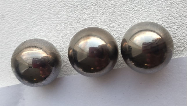
There are traces of overheating on the surfaces of all rolling elements.
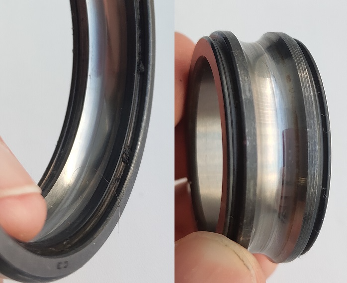
Bearing No. 2 is more interesting.

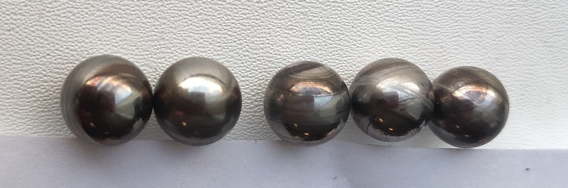
The surfaces of the tracks of the bearing rings No. 2 have a grooved shape along the entire perimeter. The defect appears stronger on the inner ring. The surfaces of the rolling elements show signs of overheating. These facts indicate such a defect as an electric burn - the flow of electric current from the rotor to the motor housing through the bearing. The displacement of the contact zones relative to the center of the tracks is also noticeable, which indicates the presence of a high axial load.
At the beginning of the article, I mentioned my mistake - I did not attach any importance to the difference between the fan speed readings on the frequency converter display with real data. Mindful of the article The electric motor burned out. Search for a reason where the engine of the same manufacturer (WEG) appeared, which made a mistake on the nameplate in indicating the connection diagram, I think that the root cause is the same here. Incorrect connection led to overheating of the electric motor, which destroyed the grease on both bearings, and on bearing No. 2 even led to an electrical breakdown of the rotor-housing. Judging by the fact that the revolutions on the converter display began to correspond to the real ones, electricians seem to have seen traces of rotor overheating during repairs and, from the experience of their mistake from the last article, changed the wiring diagram.
Since there are a lot of such cases with WEG electric motors in our company, I think that it is necessary to revise the wiring diagrams on all drives of the Brazilian manufacturer.