Loose seating of centrifugal fan bearings
Дефекты подшипников, Виброналадка, Дисбаланс, Вибрация, Вибродиагностика
Equipment repair is a must. A diagnostic specialist has to assess the technical condition of the equipment, and, accordingly, the quality of the repair. But it so happened that I expect the withdrawal of the unit from repair at my enterprise with some shudder.
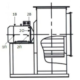
In the article Influence of induced vibration on fan bearings I pointed out the presence of false brinneling of the bearing inner ring due to induced vibration along the common pressure pipeline and the need to arrange soft inserts. The bearings on the fans have already been replaced several times and the management of the owner's workshop decided to follow the recommendations. One of the fans made a soft tarp insert. The fan was then completely disassembled again to replace the bearings. The repairers reported that the seating of bearing No. 2 on the shaft was loose and the shaft on the impeller side was bent. Further, the bearing seat on the shaft was restored, the shaft was straightened, the fan was assembled. I was on vacation, so my colleague was taking measurements. Since the fan previously had a problem with resonance in the transverse direction, measurements were carried out in the same way with the stiffening of the unit frame in the transverse direction.
RMS vibration velocity in the range of 5-1000 Hz:
RMS vibration velocity in the range of 5-1000 Hz after tightening the frame in the horizontal direction:
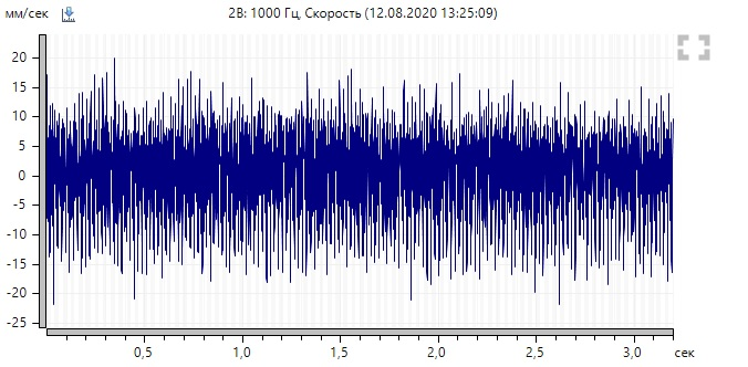
As you can see, the vibration decreased slightly after tightening the frame, but still above the tolerance of 4.5 mm / s. Let's move on to the analysis. It makes no sense to give all the spectra, we will focus on the data at points 2B and 2П.
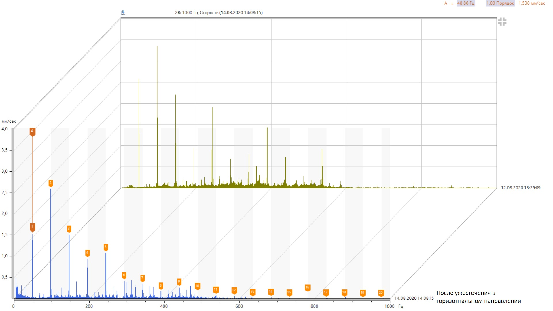
As you can see, there is no resonance and there was no need to tighten the fan frame. The spectra are the series of the revolving frequency harmonics (marked with markers). After tightening, the lateral components of the rotation frequency harmonics increased, equal to ± Fs and ± 2Fs (Fs is the separator rotation frequency). The presence of side separator components indicates wedging (uneven rotation) of the separator during the rotation of the rotor. In this case, a defect in the separator is not observed.
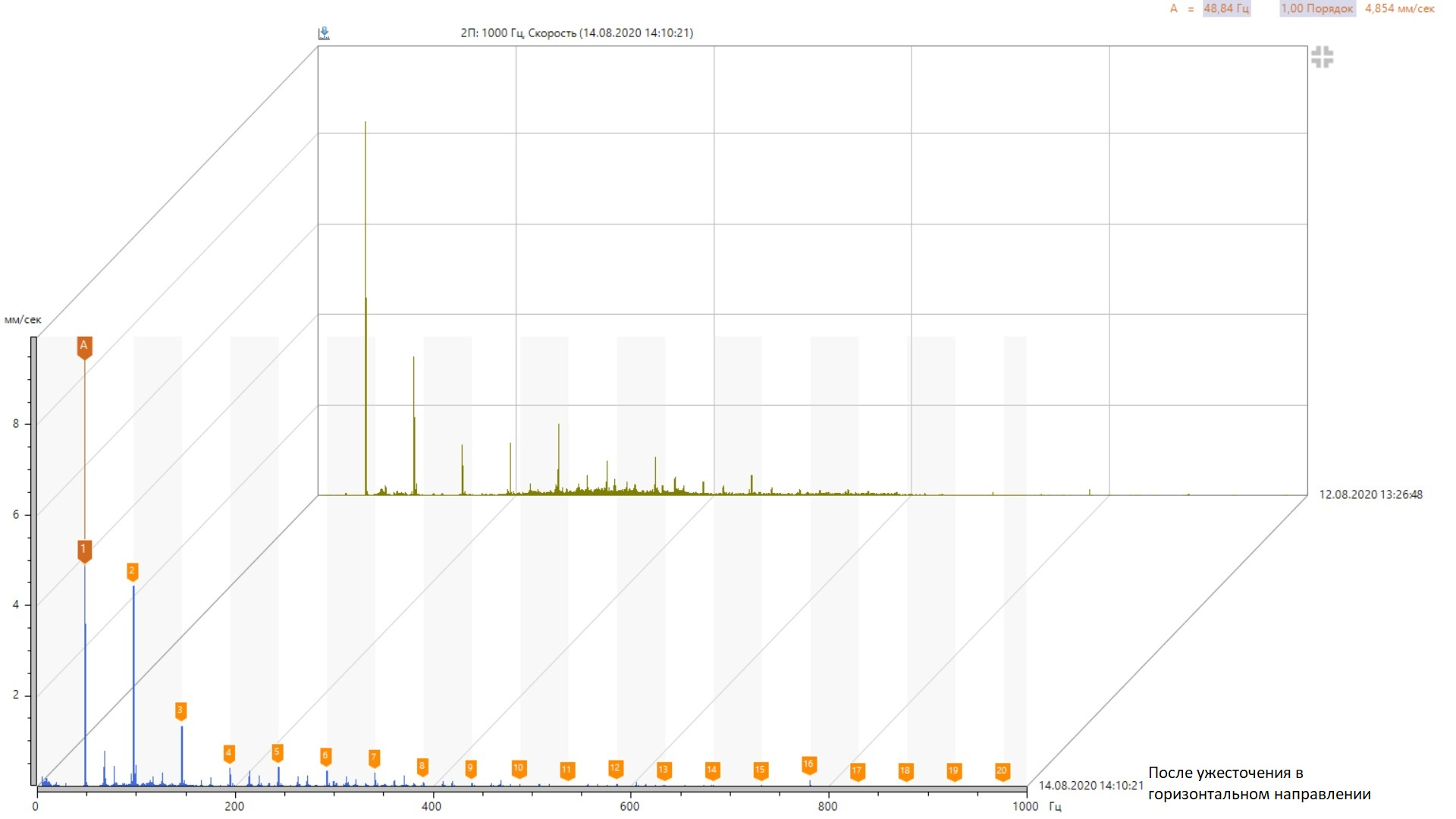
Direct spectra of vibration velocity do not give much information, so let's take a look at the time signals.
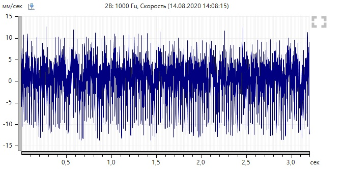
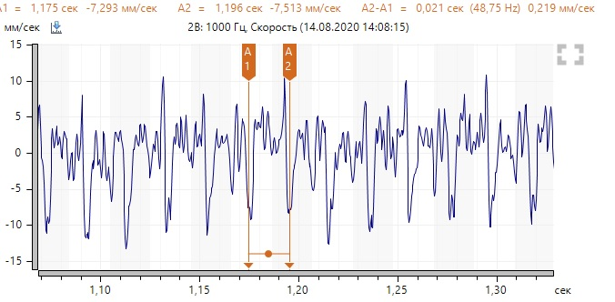
Time signals show the difference between positive and negative values of the amplitudes, which is typical for mechanical weakening. At the same time, it is noticeable that the time signal is not stable in shape from turn to turn. Knowing that there are no problems in fixing the frame, it can be concluded that the bearing fit is weakened, which is why the rotor makes chaotic oscillations. At the same time, it is necessary to pay attention to the high vibration energy (rather large values of the amplitudes of the rotation frequency harmonics), the source of which with a high degree of probability is imbalance.
Before commissioning, I demanded to partially disassemble the filter at the fan inlet to provide an opportunity to twitch the rotor and inspect the wheel for future balancing. I met little resistance from the repairmen, but all the objections and admonitions that the bearings were installed correctly were swept away. As expected, the rotor dangled in the stator of the electric motor.
Further, an act was written out indicating the rotor play in the electric motor housing due to the weakening of the bearing fit. The repairmen assured that the fit on the shaft was excellent. So it is necessary to watch the fit of the outer rings in the shields of the electric motor. The backlash in the axial direction is too large, so I also suggested checking the presence of a spring washer. The fan was taken out for another repair.
As it turned out, there was no spring washer, the outer rings dangled freely in the shields. Everything was confirmed. The seating surfaces in the shields were copper-coated, a washer was installed to eliminate axial play. The fan is assembled and running.
RMS vibration velocity in the range of 5-1000 Hz:
Vibration is expectedly high, but the spectra have changed dramatically.
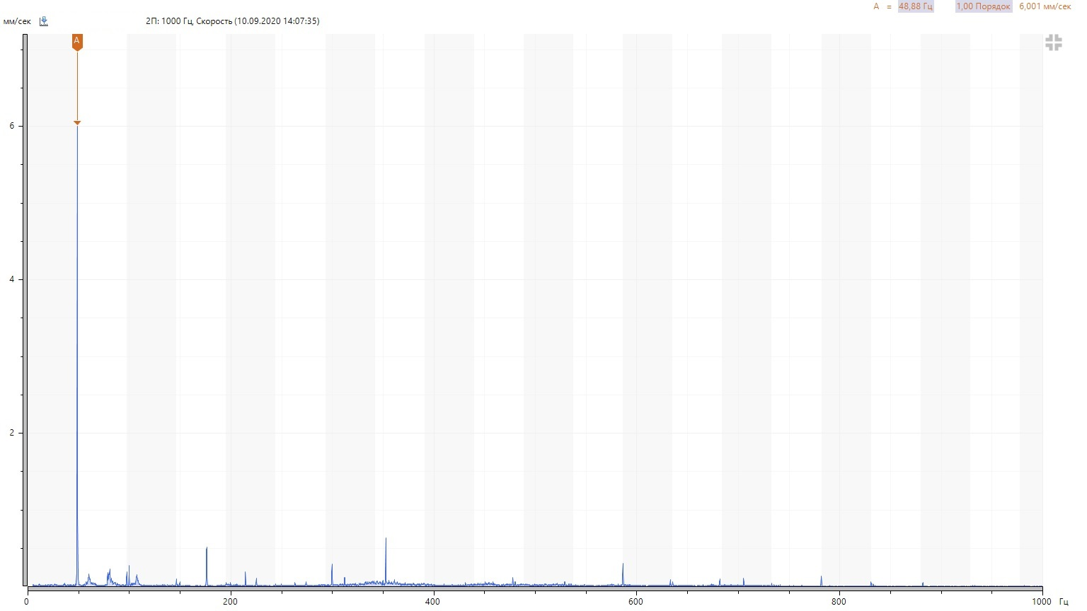
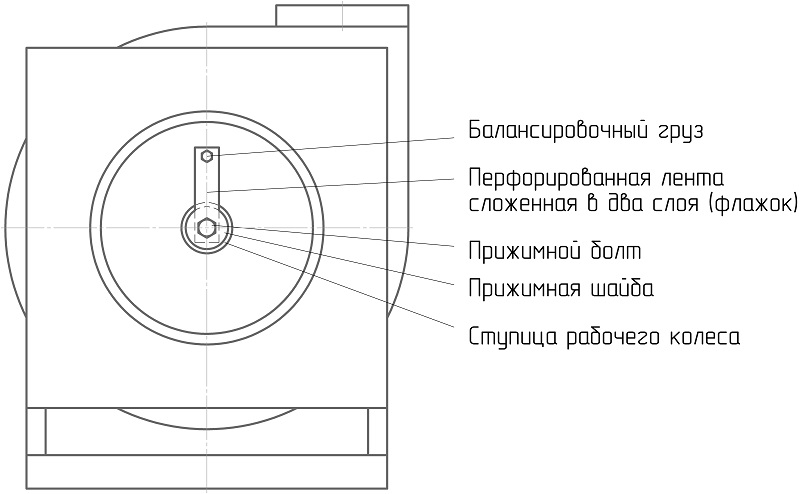
The spectrum is dominated by the turnover frequency. It needs to be balanced in place. And here is the nuance - it is impossible to allow the load to break off and get into the pipeline (there is even a filter at the suction). I balance such fans usually using brackets as a load, which I hang on the blades and fastening is provided due to high friction and centrifugal force. The advantage is the speed of manufacture and ease of installation (no drilling and welding required). But since there is a small probability of breaking such a weight, it is necessary to use another option. It was forbidden to use welding, there is no way to drill holes (the wheel is difficult to access due to the welded filter). Therefore, it was decided to balance the flag.
Balancing easily managed to reduce the circulating components to values less than 1 mm / s. RMS vibration velocity in the range of 5-1000 Hz after balancing:
Bearing No. 1 has a fairly high vibration after balancing, which is explained by the presence of a component of 176 Hz.
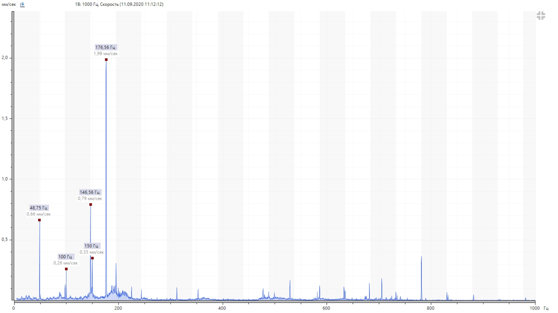
This component corresponds to the frequency of rolling of the rolling elements on the outer ring (bearing 6205). For clarity, we will construct a circular diagram at the separator rotation frequency using the time signal of the vibration velocity.
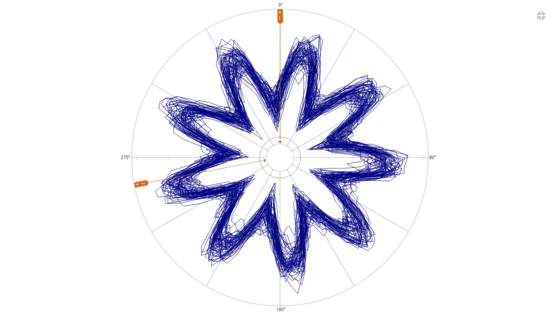
For each revolution of the separator, 9 oscillations are stable. Number of rolling elements 9 pcs. One can assume the presence of a single defect on the outer ring, but the bearing is new and the envelope and shock pulse spectra do not contain shock components.
During operation, vibration floats a little at this frequency. When the casing of the impeller blowing the electric motor is pressed by hand, the RMS vibration velocity in the vertical direction is reduced to 2 mm / s. The probable reason is the coincidence of one of the modes of natural vibrations with the frequency of rolling of the rolling elements along the outer ring, i.e. work in the field of resonance. Therefore, in the next scheduled repair, it will be necessary to confirm the resonance and tune the natural frequencies.