Two-plane balancing by two pairs of loads
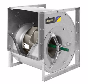
Two-plane balancing is most often carried out using calculations in specialized programs. The task is to determine the sensitivity to test weights in both balancing planes and calculate the corrective weights. But in this article I want to highlight one of the methods of dynamic two-plane balancing of a rigid inter-bearing rotor without using programs. I am sure it will seem at least interesting to many experts. As always, with a real practical example at the place of operation. A fan of a double-sided suction in a belt drive (n = 3000 rpm) will act as a test subject.
Bit of theory
As you know, dynamic imbalance is the sum of the static and moment components. The essence of this method is the sequential elimination of static and momentary imbalances by installing two pairs of goods. At the same time, to eliminate static, a symmetric pair is used that is identical in weight, radius and installation angle of loads spaced apart in two planes, and to eliminate the moment component, a skew-symmetric pair is used - two loads spaced in two planes, identical in mass and radius of installation, but located under angle of 180 ° to each other.
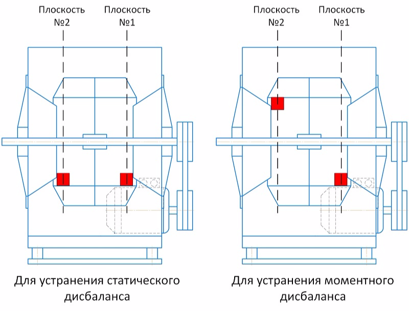
Balancing is carried out for one direction of measurement (for example, only for vertical or only horizontal). To separate the dynamic imbalance into static and moment components, we need to perform the following vector constructions:
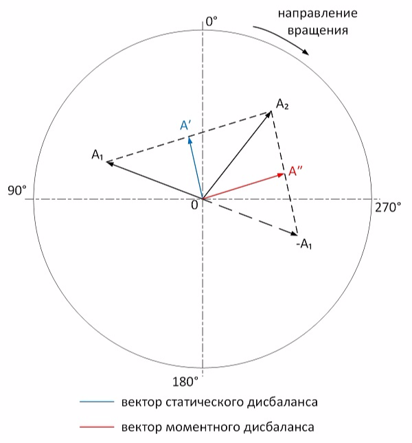
А₁ and А₂ - vibration vectors of supports No. 1 and No. 2, respectively. It is proved that the half-sum of these vectors is a static component, and their half-difference is momentary. Therefore, the vector A ′ drawn to the middle of the segment connecting the vertices of the vectors A₁ and A₂ and being their half-sum is the vector of static imbalance. In turn, the vector A ″ drawn to the middle of the segment connecting the vertices of the vectors -A₁ and A₂ (the half-difference of A₁ and A₂) is the moment imbalance vector.
Further balancing is carried out in the following order. It is arbitrarily chosen which of the components (A ′ or A ″) to balance first. An appropriate test pair of weights is installed. The obtained vibration vectors of the test run are also decomposed into components. If, for example, we first want to eliminate the static imbalance using a pair of symmetrical weights, then we build the vector of influence on the static component. By the ratio of the lengths of the vectors of the initial static imbalance and the vector of the influence of the test load on the statics, we determine the mass of test loads, the angle between these vectors determines the angle by which both loads must be moved. Calculation as with normal balancing with the only difference being that we consider both goods as one. After eliminating the statics, the balancing of momentary imbalance is likewise performed. It will become more clear on a practical example.
Practical example
It so happened that the manufacturing plant could not eliminate the vibration on the supplied fan as part of the supply unit. The equipment was taken to the plant twice, the fan was balanced twice, but the vibration remained high. I will not guess about the reasons, the most important thing is that it became possible to try out this method of balancing and dilute the routine of a vibrator with something interesting. Here I will omit the procedure of vibration diagnostics and elimination of other defects, since only balancing of the fan is interesting.
Initial data
The amplitude / phase measurements of the reverse component of vibration for balancing were made at the following points:
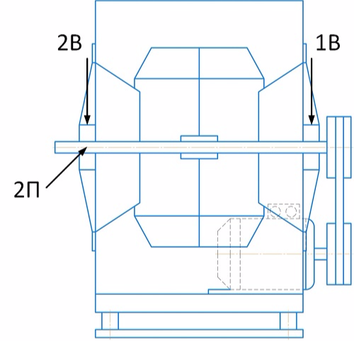
Start 0. Measurement data of amplitude / phase of the reverse frequency (vibration velocity, mm / s):
The design of the mounting of the fan support No. 1 does not allow measurements in the transverse direction. In this regard, the choice of direction for balancing is obvious - vertical. At point 2П we will monitor the change in vibration in the transverse direction.
Let us evaluate the phases of vibration in the vertical direction. With static imbalance, the phase difference at points 1B and 2B should tend to 0 °, with a pure momentary imbalance of 180 °. The actual phase difference is 109 °. Preliminarily, it can be concluded that momentary imbalance is slightly more than static. Using the balancing wheel, we perform the construction to determine the static and moment components of the imbalance:
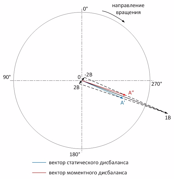
As you can see, the momentary imbalance is indeed a little more than static. We begin balancing by eliminating the static imbalance.
Static balancing
Start 1. As a test load, we install a symmetrical pair of goods weighing 4.7 grams at an angle of 0 °:
We graphically determine the vector of the influence of a symmetrical trial pair of loads on static imbalance. It will be a segment connecting the vertices of the half-sums of start vectors 0 and start 1:
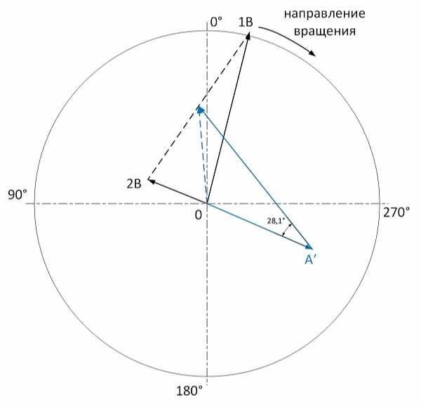
The ratio of the length of the static imbalance vector to the length of the influence vector is 0.63. Accordingly, each load from a symmetrical pair must be reduced to 4.7x0.63 = 2.9 grams. In accordance with the figure, a pair of weights must be turned 28 ° against rotation. Since I did the calculation manually, I made a mistake and got an angle of 33 °.
Start 2. A symmetrical pair of goods with a mass of 2.9 grams at an angle of 33 ° was installed:
We produce vector constructions:
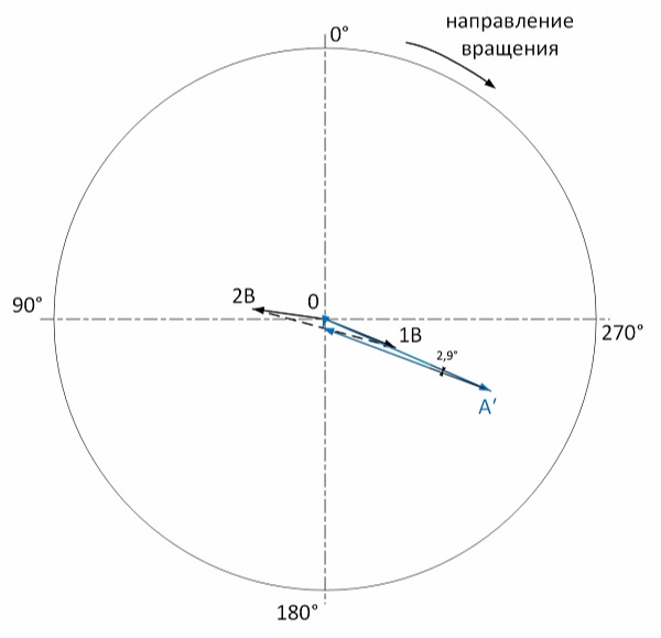
Judging by the figure, the influence vector practically fell to 0. The residual static imbalance is 0.3 mm / s. On this, the static balancing is considered complete.
Instant balancing
The vibration of start 2 is the starting point for balancing the moment component. Define it (then increase the scale by 2 times):
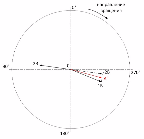
Start 3. As a test load, we establish a skew-symmetric pair of goods weighing 4.8 grams at an angle of 0 ° in plane No. 1 and 180 ° in plane No. 2:
The calculation is carried out similarly. We determine the influence vector of the trial skew-symmetric cargo pair:
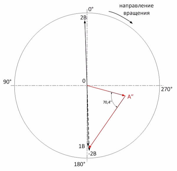
The ratio of the moment imbalance vector to the influence vector is 0.62. It follows that the estimated load is 4.8x0.62 = 3.0 grams. Additionally, it is necessary to rotate the weight system at an angle of 70 ° in rotation. Manual calculation leads to errors and in place I got an angle of 66 °.
Start 4. A skew-symmetric pair of cargoes weighing 3.0 grams was installed at an angle of 294 ° in plane No. 1 and an angle of 114 ° in plane No. 2:
Perform vector constructions:
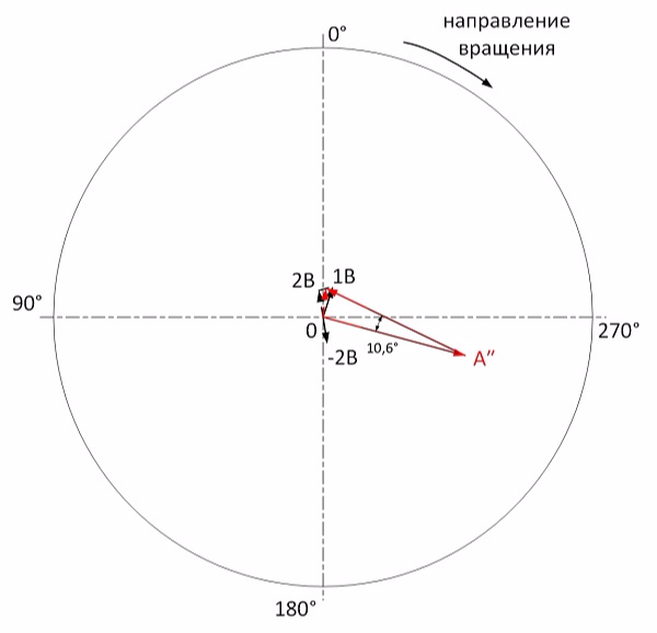
Based on the figure, the amplitude of the momentary imbalance is about 0.5 mm / s. On this balancing is over.
The initial imbalance is reduced by more than 20 times. This method of dynamic balancing with two pairs of cargoes has shown its accuracy and reliability. In the absence of balancing programs, this method is the best for balancing rigid inter-bearing rotors.
Прикрути к сайту "облачное хранилище", скину прогу для балансировки, сам ей пользуюсь так как в полевых условиях одноплоскостную балансировку тоже отрисовываю на диаграмме, а с двухплоскостной как то тягостно все это делать и пользуюсь офигенским ПО,честно с3.14зженным думаю догадываешься где)

Одноплоскостная балансировка малоинтересна с точки зрения ПО. Как время освободится - напишу ПО по двухплоскостной. Далее буду штурмовать многоплоскостную (сейчас немного с математикой застрял).
Из примера и следует желание в ПО по балансировке сразу рассчитывать вектора статической и динамической составляющей. Я часто когда считаю балансировку принимаю систему грузов (КС и СС) соответственно, как "виртуальную" балансировочную плоскость.А вообще один из тостов всегда "Ну, за ортогональность форм колебаний!".
Это несколько усложнит программу. Тогда надо выбирать какой у нас ротор - консольный или межопорный. А если нужна еще третья плоскость шкива? И чем плоха балансировка по ДКВ одиночными грузами?
Вот такая штука есть http://iwtools.ru/product/sm-02-full/
Выглядит здорово!