Vibration adjustment of the vertical pump unit ХП45 / 54-2,0
Виброналадка, Дисбаланс, Резонанс
In this article I want to talk about the difficulties encountered during vibration adjustment, the interweaving of many different defects at the rotational speed, the search for solutions to the problem, and the possibilities of the vibration adjustment specialist are not unlimited. A story without a happy ending, as always from our own real practice.
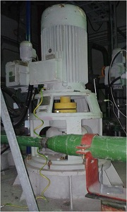
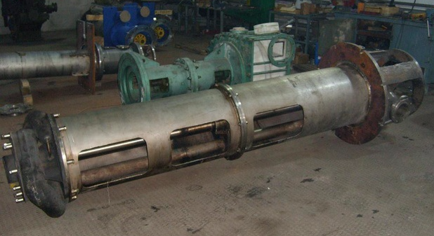
And so, we have a vertical pumping unit ХП45 / 54-2,0 (N = 30 kW, n = 3000 rpm). The main problems are increased vibration, frequent destruction of the pump bearing No. 3 (as a rule, the cage of the cage breaks). The time has come to deal with it closely. Condition - just got out of repair after a failure (bearing No. 3 was destroyed again). The upper thrust bearing and the liners of the middle and lower bearings of the pump were replaced. When dismantling, the repairmen split the impeller of the blower of the electric motor, which was welded and installed back. In addition, the presence of resonance is known - the natural frequencies were previously 50 and 56 Hz at a speed of 3000 rpm. The owner of the equipment decided to start the assembly without scrolling idling.

Vibration measurement data (RMS vibration velocity in the range of 10-1000 Hz):
From the spectra, I see only the reverse component, which most likely indicates an imbalance or resonance. Since a similar pump works nearby on the same line, it is impossible to determine the natural frequencies with an impact test. But this is not required. When working with small units, you can find out about the presence of resonance in another way. Remember what the natural frequency of the design depends on? That's right, mass and stiffness. My 100 kg mass probably will not greatly affect, and not safe. But I can increase the natural frequencies by increasing the stiffness - I press on the engine with my hand at the point 1R2. The device in the mode without averaging showed a sharp drop in vibration at 1R2 to 10 mm / s. Resonance is confirmed.
Typically, designers calculate the natural frequencies of the structure and take measures to divert them from the revolving. Therefore, it’s not bad to look for various defects such as loosening the fasteners. I check the tightening of bolts and nuts - everything is fine. I run my finger around the places where the parts are connected and find under the two opposite posts of the weakening lamp. In these places where the lantern connects with the tank cap, the finger pinches. I measure vibration at the junction of parts. On a lamp 2,4 mm / s, on a tank cover 0,6 mm / s. The gap is confirmed. Above the separation points, the radial vibration of the engine reaches 26.5 mm / s, above the struts with a rigid connection between the lamp and the tank cap, the radial vibration of the engine is 8.8 mm / s. Since the unit is urgently needed, there is no time to look for the cause and scrape the cover or lantern. Above places with a lack of fit in the lantern, I install previously prepared jacks (disputes between the attachment points to the tank and the attachment area of the upper pump bearing). I’m not pulling hard, looking at the readings of a vibration analyzer operating in the mode without averaging. The task is only to divert the natural frequency from the reverse and in no case to deform the lamp. Vibration instantly drops to 4.5 mm / s, with a further tightening of the jacks it falls slightly. I return the pull of the jacks to the moment where the vibration began to decline slightly. We know that the vibration we are measuring is a response at the measurement point to some acting internal forces. And since this response depends on the rigidity, there is no point in increasing it and hiding the defect.
We measure vibration after the detuning from resonance:
Vibration is on the verge of normal (tolerance of 4.5 mm / s); as before, the reverse component makes the main contribution to the spectra. I recommend balancing. The owner of the equipment ordered the motor to be idled.
Repair personnel disassemble the coupling halves by gluing a reflective mark on the engine coupling half and measure the amplitude / phase of the reverse frequency. Amplitudes float 1.8 ... 3.8 mm / s, with phases similarly - a spread of more than 40 °. I ask you to briefly turn off the running standby pump for a short time due to the strong influence of vibration induced through the pipeline. The amplitudes and phases have stabilized, it is possible to perform measurements at idle (Amplitude / Phase, mm/s / °):
The phases show that the balancing will be simple, since the imbalance is mostly static.
Remove the existing load (M4 bolt with washers and nuts) with a mass of 13.3 grams from the impeller of the engine blower. with an installation angle of 0° (I specially installed a reflective mark) and perform similar measurements:
We see that the sensitivity to the load is high. Affect the high speed and low rigidity inherent in all vertical units.
Calculations are carried out in vector form on a piece of paper with a balancing wheel manually. It is possible, of course, according to the program in the device, but it is important for me to visually observe the vector of imbalances and the influence of goods. So taught, so used, and the device on hand - Quartz. I do not use programs on a PC for one- and two-plane balancing, as I always carry out calculations at the place of installation of the equipment and do not waste time going to the office. And now to vector constructions:
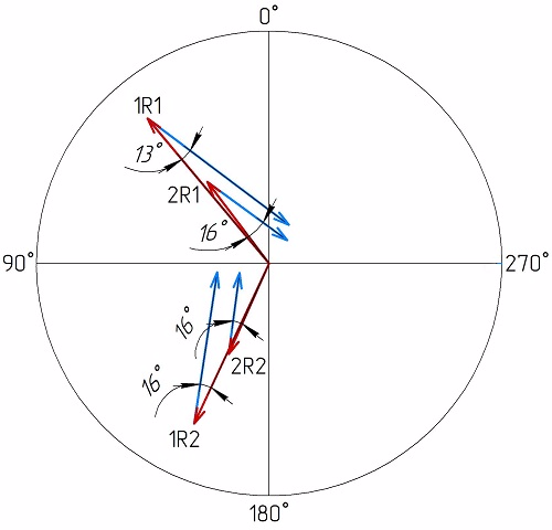
The figure shows that the load must be slightly increased and rotated by 15°. Unfortunately, the repairmen couldn’t drill a hole for the jewelry under the new position of the load - they made a little mistake both in radius and in angle. Given the high sensitivity, the measurement with a load of 14.8 g. at the installation angle of 15° in rotation:
According to the calculation, if everything had been done perfectly, the maximum vibration would have been 0.8 mm / s. Here, to be honest, I was too lazy to make changes and make another balancing start. I give the command to connect with the pump and get the following data in the collection:
That would seem to be all. But no. The next day, when measuring, I received such data (RMS vibration velocity in the range of 10-1000 Hz):
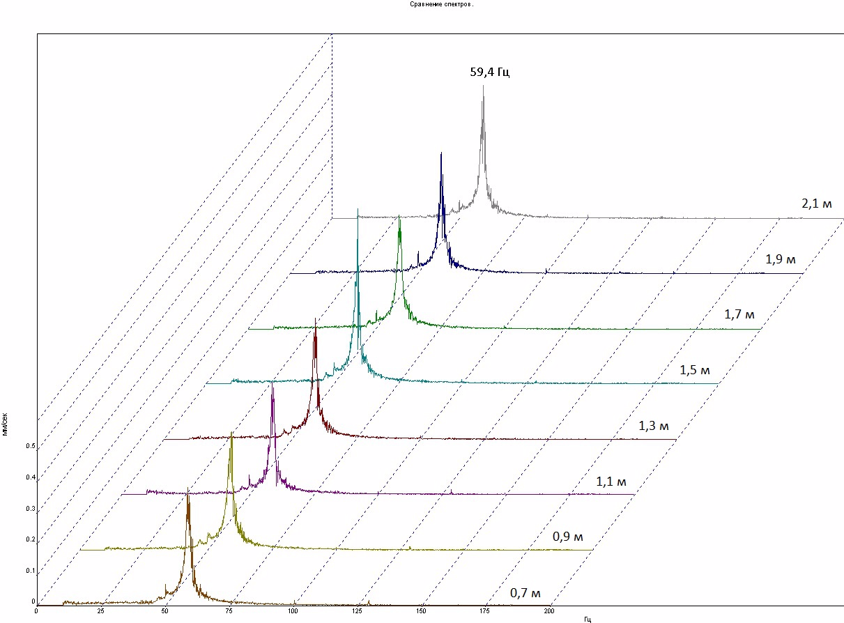
What changed? The pump switches on automatically when the level in the tank reaches 2.1 m and turns off at the level of 0.7 m. Measurements after balancing were carried out with the tank full. And on this day, measurements were taken at a lower level. To determine the influence of the level of the medium in the tank (L, m) on the vibration state of the unit, I conduct a series of measurements (RMS vibration velocity in the range of 10-1000 Hz):
The effect is quite obvious. We will determine at what frequency changes occur.
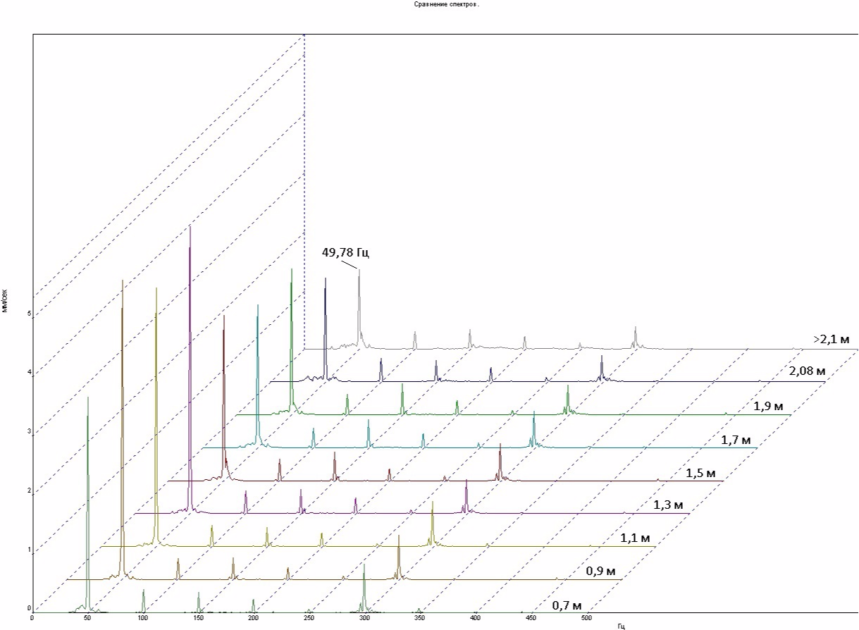
We see that changes occur only at the revolving frequency of 49.78 Hz. It was recorded that with a decrease in the level of the medium in the tank below 1.5 m, the general vibration level has a “floating” character with amplitude fluctuation at the rotational speed. So, with a level in the tank of 2.1 m, the vibration amplitude varies in the range of 1.8 - 2.0 mm / s. At a level of 0.7 m - in the range of 2.0 - 6.7 mm / s.
An analysis of natural frequencies at points 1R1 and 1R2 was also performed.
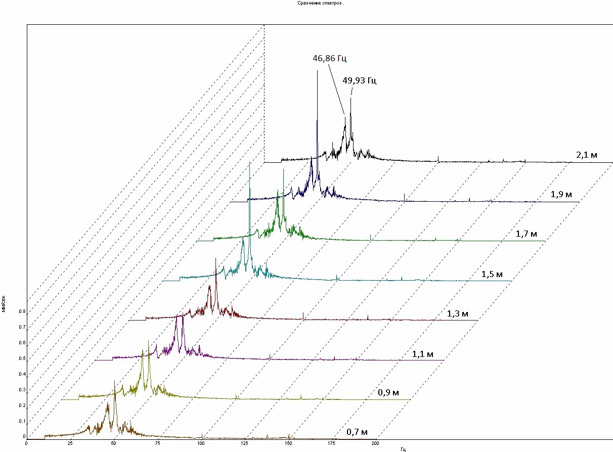
From the spectra it is clearly seen that in the direction R1 the aggregate operates in the resonance region. In the direction of R2, the natural frequency is far enough from the speed of rotation. How can we explain the increase in the amplitude of vibration and strong fluctuation with a decrease in the level of the medium? Only one thing comes to mind. As the level decreases, the rigidity of the lower part of the unit decreases, which leads to the convergence of the peak of the natural frequency and the rotation frequency, that is, to enhance the resonance. Excitation of the medium in the tank sways the lower part of the unit a little, which also leads to a change in stiffness. The natural frequency of the structure either approaches the reverse, then moves away. Accordingly, it is necessary to tighten the lower part of the unit. When searching the Internet for problems with HP pumps, I found an example of the modernization of such a pump, which I proposed to make to the owner of the equipment.
And a little about bearing number 3. Low vibration on it is deceptive - it is necessary to take into account very high rigidity in this place. Here is the spectrum of the envelope of the vibration signal:
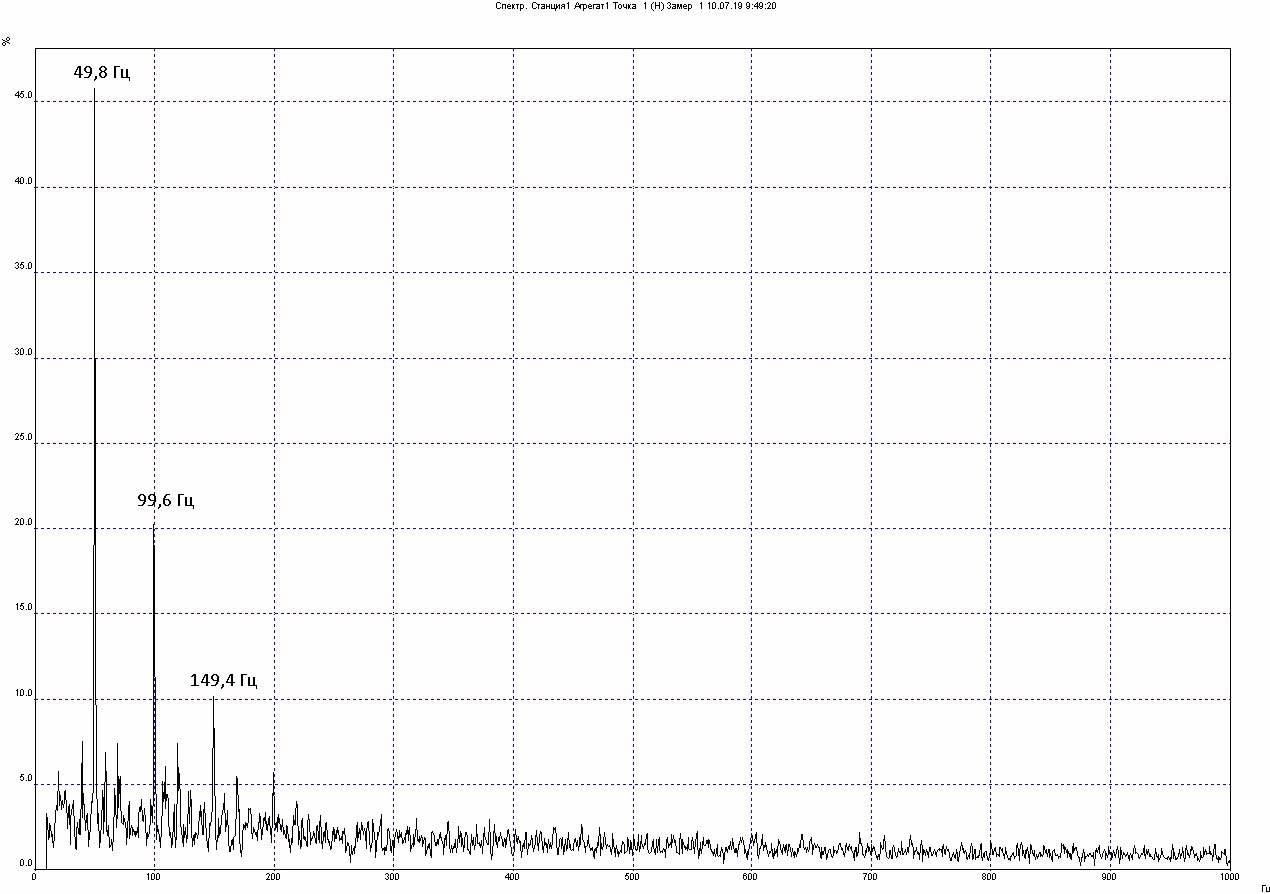
The harmonics of the reverse frequency that rapidly decrease in amplitude are characteristic of a defect such as a battle shaft. When working, I brought the handle to the coupling - it hits hard, the defect has a place to be. He shared this fact with a pump repair specialist. He said that the reason is in a crooked shaft. There were attempts to straighten it, but it didn’t work out so much, we need to order a new one.
In fact, a lot of effort has been expended, the vibration state has been significantly improved, but it was not possible to solve all the problems to the end. They ran into design flaws. If any attempts are made by the owner of the equipment to solve the problem, I will certainly update the article.
Что плохого в Кварце при балансировке?
Кварц замечательный прибор для своего времени. Даже по сей день импортные дорогие приборы не могут похвастаться многоплоскостной балансировкой и в этом проигрывают Кварцу. Но в Кварце не хватает контроля при проведении балансировки - визуализации. Да и ручной ввод данных для балансировочных расчетов не удобен. А в остальном придраться не к чему.