Supply fan balancing
This article presents a two-plane balancing fan on a single shaft. A practical example of balancing is shown, the calculation of which is done without using software. Comparison is made with the calculation results on a PC.
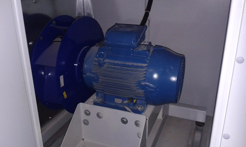
We have a supply fan N = 5.5 kW, n = 2860 rpm. Condition - after repair. They said that the electric motor burned out due to seized bearings. Bearings replaced, motor returned from rewinding windings. RMS measurement data of vibration velocity in the range of 10-1000 Hz:
Vibration tolerance 6.3 mm / s. We fix the excess. Spectrum of vibration velocity at point 1P:
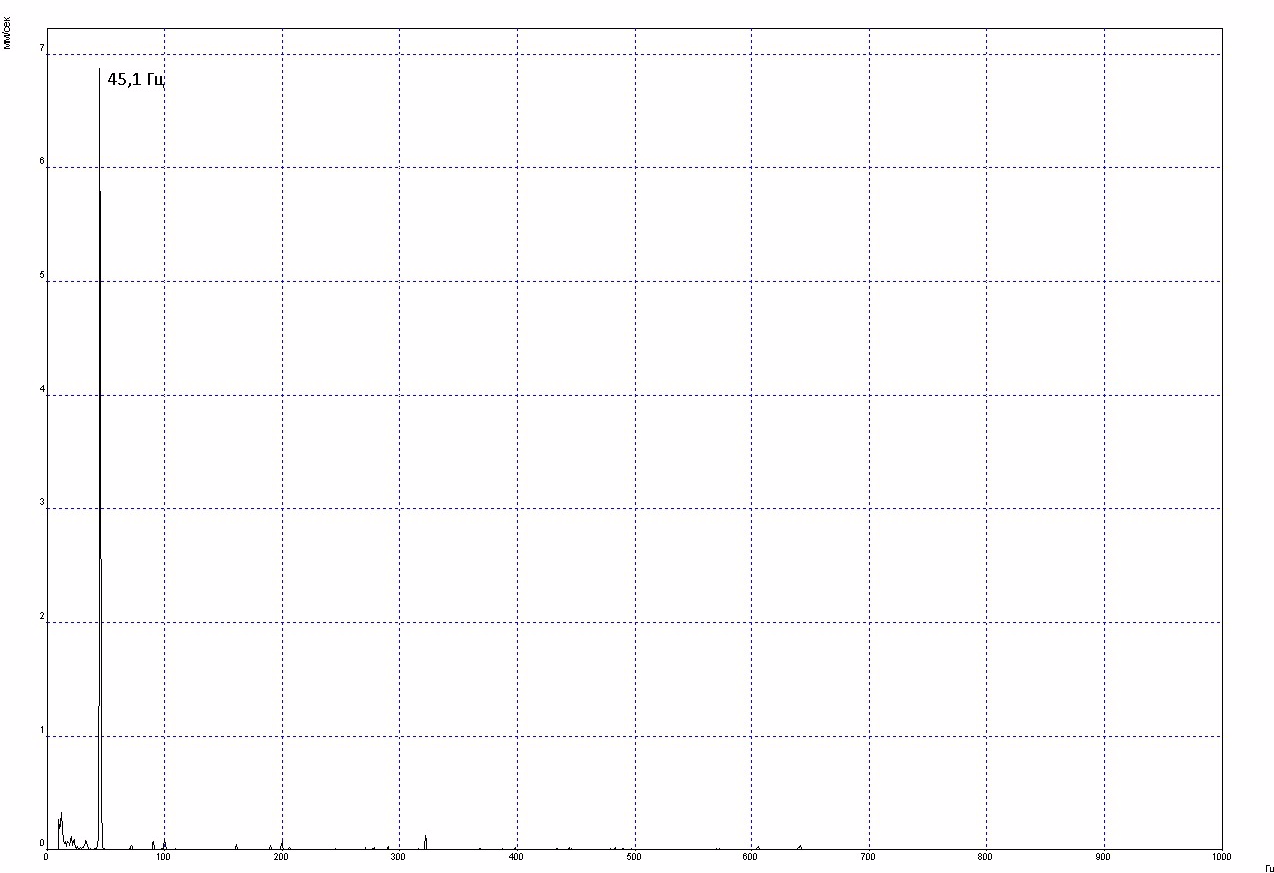
Similar spectra at other control points - everywhere, the main contribution is made by the reverse frequency of 45.1 Hz. Imbalance in all its glory.
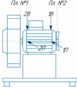
We pass to balancing. As is known, balancing calculations are based on a comparison of unbalance vectors and influence vectors from the test load. We begin balancing from the plane of the impeller by removing one of the existing factory weights. Fan circuit with measuring points and balancing planes:
Start 0. We measure the amplitude / phase of the reverse component of the initial vibration:
Start 1. Remove the factory weight 2.5 grams from an angle of 200 ° in the plane No. 1:
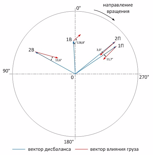
On a sheet of paper with a balancing circle (polar coordinate system), we produce vector constructions for determining the influence vectors of 0 start relative to start 1:
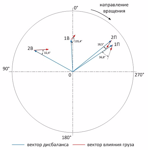
As you can see, the sensitivity to this load is small. The influence vector at point 1B is at a much larger angle to the imbalance vector than at other points. Let's try to turn the influence vectors by 40 ° in rotation and increase their length by 3 times.
Start 2. Install the load of 5.0 grams at an angle of 340 ° in the plane number 1:
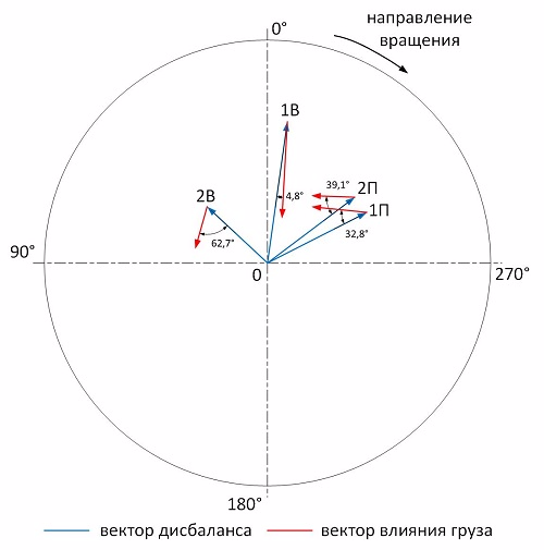
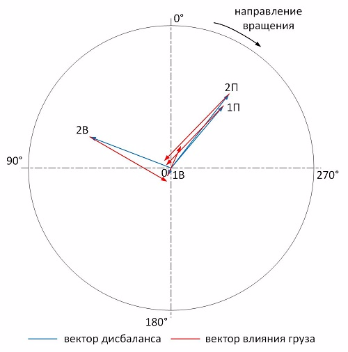
Start 2 relative to start 1:
The influence vector 1B practically did not change, although the other vectors turned in the desired direction, but it does not make sense to continue balancing in this plane. Point 1B is not sensitive to plane No. 1. In this regard, it was decided to leave everything as it is in plane No. 1 and go to plane No. 2. By plane No. 2, the impeller for blowing the electric motor was chosen as the closest available to point 1B.
After removing the protective cover, I see that the plastic impeller of the blower is damaged - a strong geometric deformation of the part from exposure to high temperatures. It is strange that the repairmen did not replace, but the more interesting the balancing.
Start 3. We set the load of 9.9 grams at an angle of 310 ° in the plane number 2:
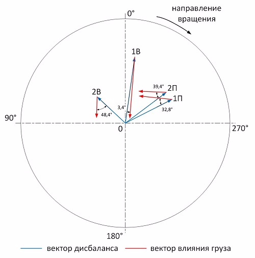
Start 3 relative to start 2:
Vibration is already less than the tolerance of 6.3 mm / s and some balancers would stop there. But we will continue. We will reduce vibration as much as possible at point 1B, and we will balance the remaining points in plane No. 1 (for the first starts we have normal sensitivity there). From the ratio of the imbalance vector 1B and the influence vector from the load at start-up 3, I calculated that the load should be increased by about 1.4 times. We will not change the angle, since the load is hung on the impeller blade (a total of 7 blades with a pitch of 51 ° around the circumference).
Start 4. We remove the load of 9.9 grams from an angle of 310 °, hang a load of 13.4 grams at an angle of 310 ° in plane No. 2:
Start 4 relative to start 2:
We go back to the plane number 1.
Start 5. Remove the load of 5.0 grams from an angle of 340 ° in the plane number 1:
Start 4 relative to start 5:
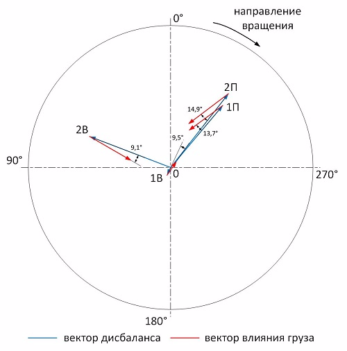
We have a very good sensitivity to the five-gram weight. It remains to increase the weight by about 2 times and rotate 10 ° against rotation.
Start 6. We hang the load of 9.5 grams at an angle of 350 ° in the plane number 1:
Start 6 relative to start 5:
After balancing in the No. 1 plane, we got a sensitivity at 1B, which slightly smears the picture. But let's stop there. To summarize, for balancing the fan in the plane No. 1, the factory load of 2.5 grams was removed from an angle of 200 ° and a new load of 9.5 grams was installed at an angle of 350 °, in plane No. 2 a load of 13.4 grams was installed at an angle 310 °.
RMS vibration velocity in the range of 10-1000 Hz after balancing:
In total, 6 starts were needed for balancing. For the sake of interest, I performed the calculation in the Goldin program according to the data of launches 1, 2 and 3. According to the results, 9 grams at an angle of 355 ° are required to be added to plane No. 1, 16 grams at an angle of 310 ° to plane No. 2. In this case, the residual vibration should be:
Manual calculation gives similar results, although the worst, and it required 2 times more starts. But on the other hand, with manual calculation, the entire balancing process is controlled by a specialist. It was also interesting to learn about the effect of imbalances on sensitivity at point 1B, which will undoubtedly replenish the pool of my knowledge.
In addition, I will say that this fan worked for two days, until it burned out again. And this is also my fault (didn’t you notice anything unusual in this article?). But more on that later .