Diagnostics of electric actuator valves by electrical parameters
Мощность, АТЭ ТС-3000, Диагностирование, Арматура, Диагностика, Крутящий момент
First of all, in the nuclear power industry, but also in other industries, the direction of valve diagnostics is developing. The lion's share of all valves is occupied by valves with an electric drive and, depending on the type of power unit, their number can vary from 3000-4000 to almost 6000 units per power unit. Although not all fittings directly affect safety or power output, failure of just one mechanism is enough for fatal consequences, which, given the enormous laboriousness of repairing fittings located in an unsecured section, translates the diagnostics of valves from the category of "pampering" into a fairly serious science.
Timely and correctly built valve diagnostics allows you to kill two birds with one stone: transfer part of the reinforcement for repair according to the actual technical condition instead of repair according to the regulations, and also track its condition during the overhaul period to prevent failure due to a critical defect. If everything is very clear with the second point, then the first allows not only saving money by increasing the turnaround time, but also minimizing the likelihood of failure due to poor-quality repairs, freeing up labor resources to repair other critical equipment.
The principle of diagnosing electric actuator valves by electrical parameters is to use the installed electric actuator as an indicator of the valve state, since any change in the moment of resistance to movement is reflected in the electrical parameters of the electric actuator (active power) and can be recorded and analyzed, plus the state of the electric actuator itself is assessed. However, this method allows, first of all, to qualitatively assess the state of the reinforcement, since the only regulated characteristic for the valve is the torque. Torque can be obtained in two ways: by placing a torque transducer between the actuator and the valve, or by performing the initial calibration of the actuator on a torque bench to obtain a calibration characteristic. The second method has become widespread, and we will stop here.
Valve diagnostics, as a rule, is carried out both at the place of its installation using portable (mobile) diagnostic tools, but such diagnostics does not allow with reasonable accuracy to quantify the torque developed by the electric drive during its working stroke when torque switches are triggered, which does not allow them customization. This problem is solved by installing the electric drive on a special stand equipped with a force sensor and a brake unit to simulate valves. An example of such a stand is ATE TS-3000 manufactured by JSC Atomtekhenergo, popularly referred to as "Bear", which is quite consistent with its type and even more weight.
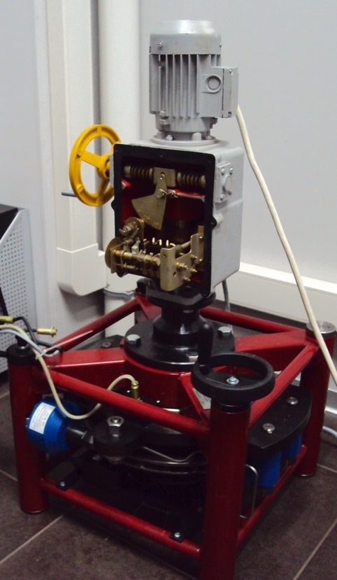
After installing the electric drive on the stand, the calibration characteristic (the dependence of the active power on the torque developed by the electric drive) is taken, as well as the torque switches are set.
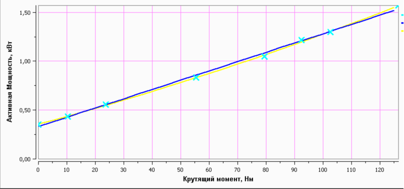
The presence of such a characteristic makes it possible to automatically recalculate the active power recorded at the test site in the torque without removing the electric drive from the valve. As practice shows, each electric actuator from the series, although it has an individual characteristic, but in general they are similar to each other, which allows you to turn a little trick: in order not to remove the electric actuator from each unit of the valve for installation on the stand and subsequent calibration, you can make a sample from several units of the same type of drives (the more, the better), calibrate them, average the obtained characteristic and apply to the entire series of electric drives. This approach makes sense when the number of drives of the same type is in the tens, hundreds or more, but with reservations: in this way, only serviceable mechanisms without modifications with a comparable service life and periodic repeated basic tests of electric drives can be compared. You cannot apply the characteristic obtained on the new electric drive to the one that has already worked for ten years and has gone through more than one repair, since the error can be huge.
Diagnostics of valves at the place of installation can be carried out either directly next to it from the gate valve electric drive unit (BEZ) or from the control cabinet in the low voltage switchboard. The measurement principle is the same: using a clamp meter and voltage measuring probes, the main electrical signals are read: current and voltage, which are converted by software into active power, and in the presence of a calibration characteristic, into torque. If there are control cables of limit and torque switches in the control cabinet, their readings can also be taken, which will expand the analysis capabilities. The output is the dependence of the torque (active power) on time in the form of a cyclogram. The essence of diagnostics is reduced to the analysis of the cyclogram at characteristic points and comparison with the reference cyclogram, previous measurements, with positions of the same type. General view of the sequence diagram of shut-off valves when closing:
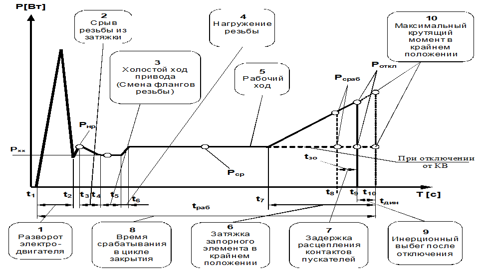
In addition to the measured characteristics shown in the figure, a large number of calculated parameters are used, the set of which can vary depending on the "depth" of diagnostics, software and hardware used. The main design parameters include: smoothness (%), difference in stroke time when opening / closing (%), time between characteristic points. Diagnostics of valves at the place of installation is carried out with a frequency corresponding to its category, which is determined by a number of characteristics, including on the basis of the impact on safety, frequency of operation, etc.
These are, in fact, the main points that I would like to tell. Rebar diagnostics is not limited only to the analysis of the obtained cyclogram and is widely used, in particular, methods of ultrasound diagnostics, thermal imaging control, etc., but these are topics for other articles.