Why you shouldn't diagnose by current
Диагностирование, Арматура, Диагностика, Мощность, Крутящий момент
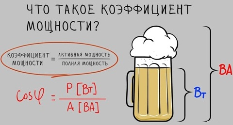
If you open any passport for electric actuator valves, technical specifications, operating instructions, in the controlled parameters you will not find a single mention of current or active power, since almost the only quantitative characteristic that evaluates the operation of the valve at characteristic points is torque. Accurate determination of the torque of an electric actuator using direct measurements is a rather complicated or time-consuming procedure, therefore, when diagnosing valves, an electric actuator is used as a kind of sensor from which electrical parameters are taken and analytically converted into torque or used in a "raw" form to assess the state of the mechanism. At the moment, there are two main, at first glance, similar, but completely different in essence, methods of diagnosing by electrical parameters: by current or active power. It would seem, what is the difference if one follows from the other? Do not count how many times my soft spot was heated by the question of equipment owners: "Well, what about the currents?", "What current?" and other derivatives, and all because I consider current diagnostics an outdated and unreliable method. So why is active power better? It is directly related to torque through the equation:
It is no secret that the active power, in turn, is directly related to the current consumption and the supply voltage of the network, but for some reason some forget that there is another variable in the equation, and someone even considers it constant, this variable is a coefficient load, or cosφ (the so-called cosine phi), that is, the equation takes the following form:
According to Wikipedia, cosφ is a dimensionless quantity characterizing an alternating electric current consumer in terms of the presence of a reactive power component in the load, that is, cosφ = P / S, where P - active power (W), S - apparent power (VA). The reactive power Q is also allocated.
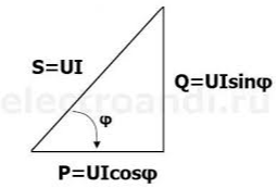
Active power in this case is nothing more than useful power, which is used to perform useful work (creating torque on the motor shaft). The reactive component does not perform work and is spent mainly on heating, although it serves to create an electromagnetic field.
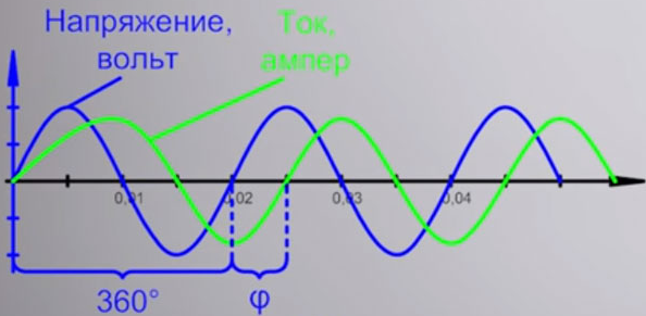
The angle φ itself is essentially the angle between current and voltage. It is no secret that this angle depends on the nature of the load: with active-capacitive current, the voltage is ahead of the voltage by an angle from 0 to 90 degrees, and with active-inductive current, the current lags behind the voltage by the same angle. For AC motors, the latter option is characteristic.
The power factor is not at all constant, but strongly depends on the operating mode of the electric motor (load value) and varies according to the individual characteristics. For example, the dependence of the power factor on the load for the AIR71A2U2 electric motor looks like this:
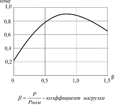
As can be seen from the characteristics, the power factor at different operating modes of the electric motor can change several times: from 0.1-0.2 at idle to values close to 1.0 at rated load. The larger the motor, the generally higher the maximum power factor. In real measurements, this change can also be seen if desired.
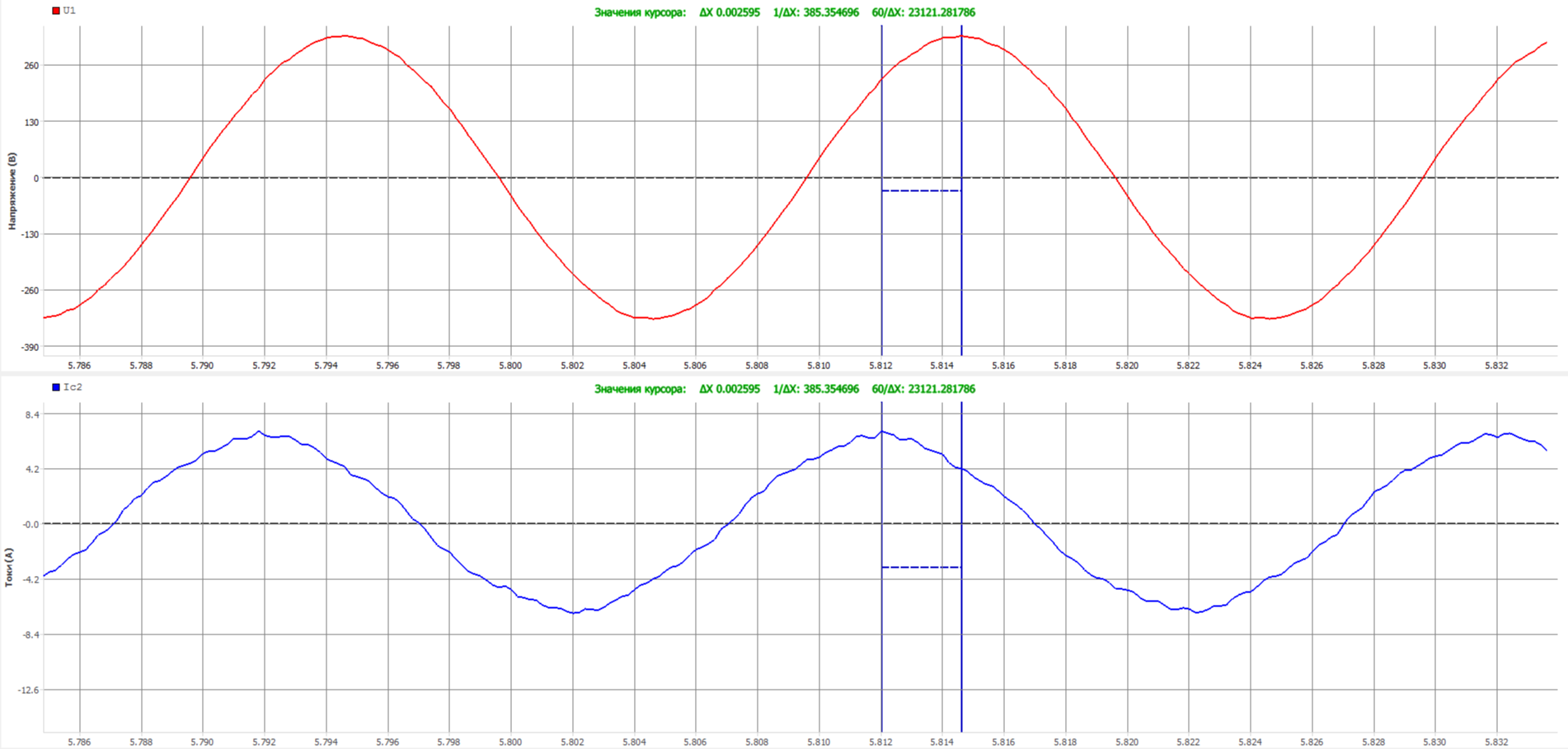
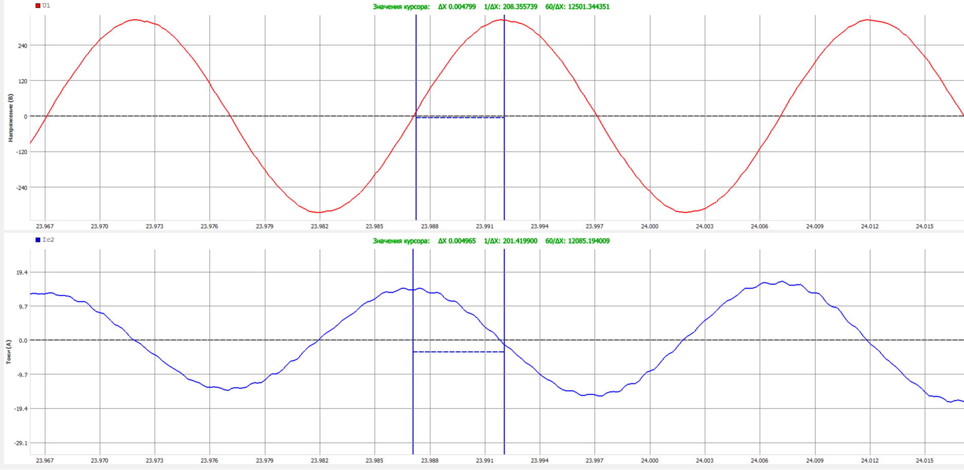
As noted above, the angle φ characterizes the shift between current and voltage. Above are two graphs of the same valve in different parts of the stroke: uniform movement and end of the seal. It is possible to qualitatively estimate the change in the shift between the time intervals between the peaks of the corresponding sinusoids. In the first case, the displacement is 0.002 s, at the end of the seal at maximum load, the displacement is already almost 0.005 s. With a strong desire, you can quite accurately quantitatively calculate the angle, but in this case it is only important that it has changed, and significantly.
Imagine a situation in which an electric motor is running at light load and close to idling with a power factor of, for example, 0.2. After that, the load increases up to the rated parameters with the declared cos φ = 0.8. The power on the shaft of the electric motor (and with it the moment) can change several times, but, based on the above ratio, the stator current will not change. Thus, if you make diagnostics based on current signals, you cannot see the changes in this case.
A huge number of electric drives that control valves during sealing not only do not show an increase in current, but on the contrary - it often drops due to a more rapid increase in cos φ as it approaches the nominal mode. It is unacceptable to adjust the torque switches, focusing on the ratio of the draft current to the working one. The only approach in which such a setting can take place is the experimentally derived ratio for a specific link "electric actuator-armature".
However, to this day there is a methodology that establishes that all fittings must be tuned according to one criterion: the tightening current should not exceed the working current by more than 1.5 times. The ratio of 1.3-1.5 is considered the norm for gate valves with a power of up to 11 kW, and the operating current should not exceed the rated one. Oddly enough, this technique has a huge number of followers, despite the internal contradictions in the technique itself. In the minds of most workers, for simplicity, an even simpler parameter has been established - the ratio of the draw current to the worker should be 1.3. That's all the simple arithmetic, but let's see why it is not true with real examples.
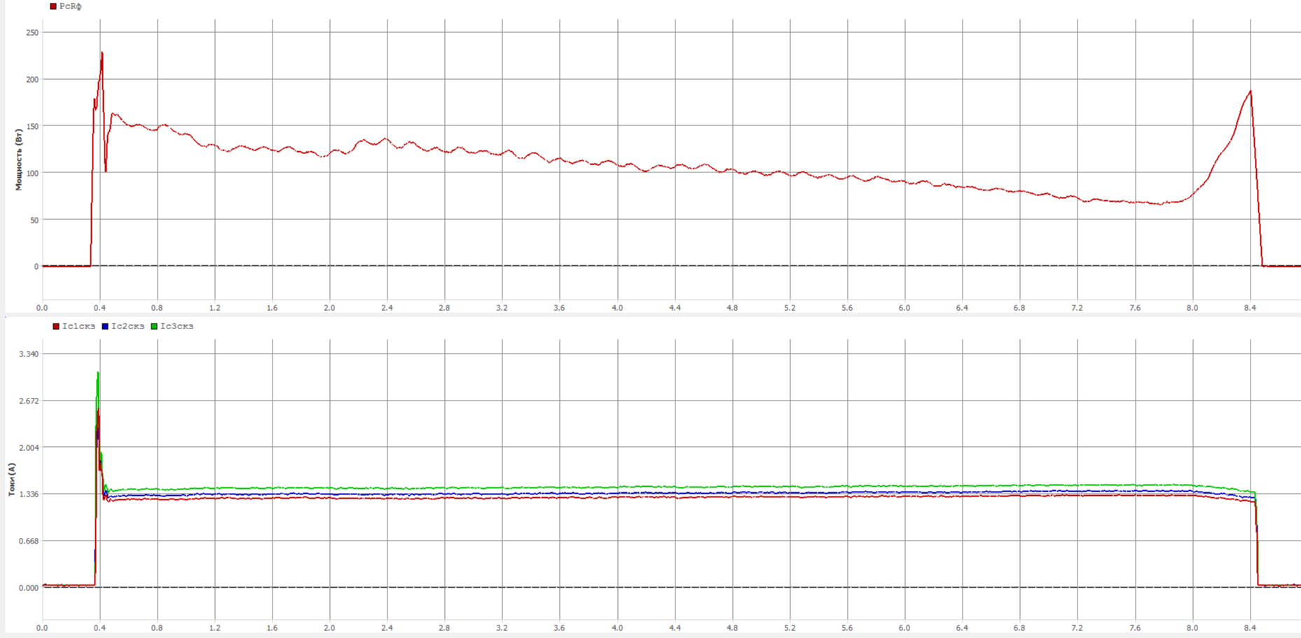
Below are the cyclograms of currents and active power of EPA with electric motors of type 4AC 80В4A5 (drive 2-OB-03)
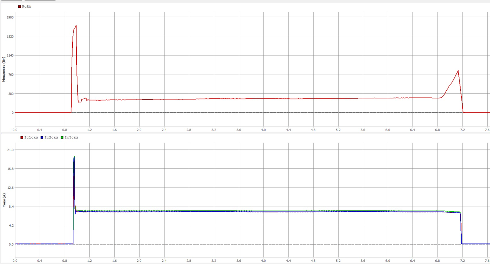
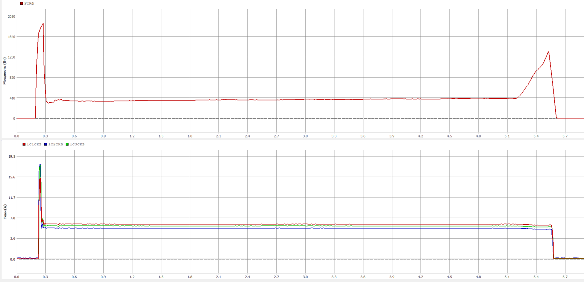
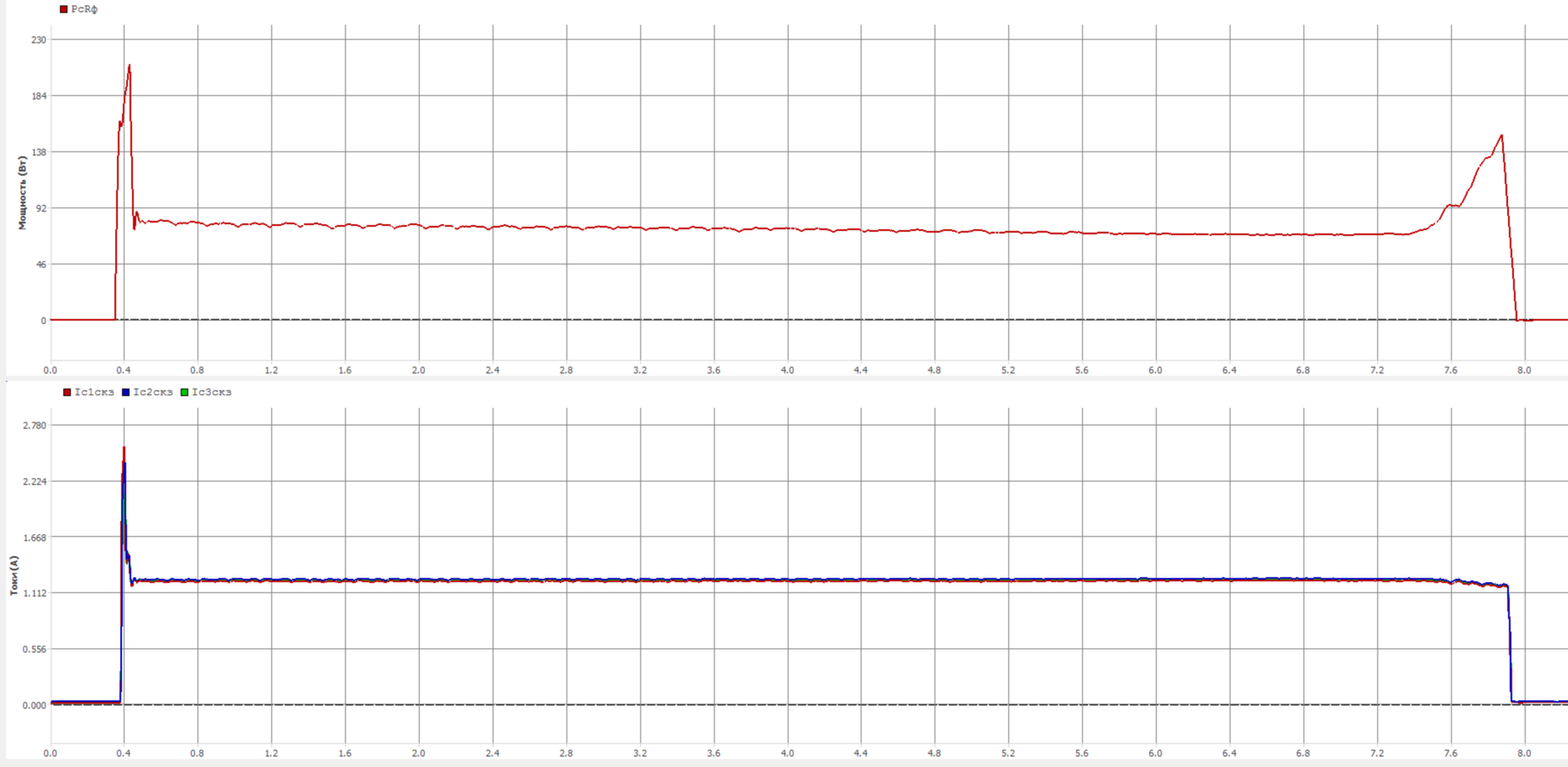
As you can see, during compaction, the current not only does not grow, but even drops. Separately, it should be noted that the rated power of these electric drives is 1.7 kW, and the rated current is 6.2 A. If you pay attention to the first figure, the average active power of the working stroke there is about 275 W, which is more than 6 times less than the rated values, while the average current is about 7.2 A, which is already 20% higher than the nominal. In the second figure, with an average power of 370 W, the average current is about 6.5 A, that is, the higher the power (up to the nominal value), the lower the operating current. With absolutely normal valve behavior, we go beyond the rated current and reject the valve, is this correct?
Here, for example, examples from fittings with Czech electric actuators MOA OC 63-25 I 40-25 with electric motor 4АС 56В4А5
There are a lot of such examples, especially among drives of frame size B. In frame size A, it is generally difficult to achieve a noticeable increase in current in operating parameters, while at the working stroke it is almost always higher than the nominal value. When I was young, I had a chance to carry out bench tests of a 2-OA-18 electric drive with a 4AC 56V4A5 electric motor (rated power 0.18 A, current - 0.9 A), which has a defect in the brake assembly. When installed on the stand, the idle power turned out to be about 300 W and the current in the region of 1.3 A. The brake unit was removed and the power dropped to 120 W, the current was 1.3. We removed the electric motor from the drive and ran it separately, having received 40 W of active power and a current of 1.3 A. That is, no matter what we do, the current is always one and a half times higher than the nominal and this is considered normal operation.
This behavior is not always met, and you can see the opposite picture, when the current rises quite rapidly.
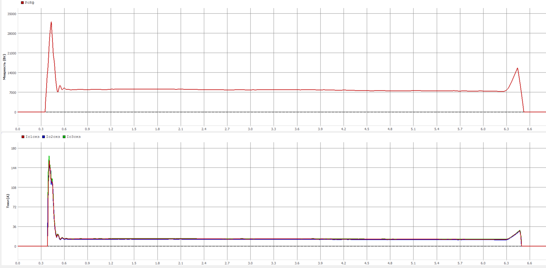
Above is a cyclogram of currents and active power when closing an ESP with an Auma SA 25.1 11 kW electric drive and an ADI0 132-2-W40 ED with a minimum torque switch setting for closing (2.5 times lower than that specified in the TU for the armature), where the ratio of the draft current to the worker is 2.2, which is significantly higher than 1.3 from the methodology. Need to reduce? But there is nowhere to reduce, because even so there is a minimum at which the clutches periodically received false triggering during the working stroke.
From the above, we can make an unambiguous conclusion that diagnosing and adjusting torque switches for current is untenable as a method. If the settings of the above positions were carried out according to this technique, the first part would be turned into minced meat, and the last would not close at all, and it is doubtful that this setting would be possible at all, since the clutch adjustment range would not be enough.
The analysis of the current stroke will also cause great difficulties, since many fluctuations that are reflected in the active power are not visible at all on the current signal and there are quite a few examples when the smoothness of the stroke of the same position in terms of power does not even reach 50%, while the current goes far beyond 80, or even 90%. If you want to conduct a spectral analysis, you simply will not see some frequencies on the current signal.