Collisions in the claw clutch
Удары в муфтах, Расцентровка, Вибродиагностика

Cam couplings with an elastic damping element are quite common in enterprises, lower requirements are imposed on their alignment than for elastic sleeve-finger couplings, but from personal experience this does not save from problems that arise with them. In this article, we will analyze a practical example of diagnosing a defect in a double-joint cam clutch.
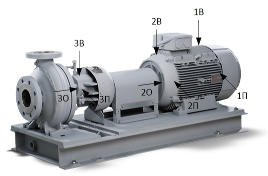
So, a call for extraneous noise from the heat carrier circulation pump of the HPK-LS 080-200 boiler room (7.5 kW). The rotation speed is regulated by the VFD, we carry out vibration measurements at an operating speed of 619 rpm and 1393 rpm. It is not possible to determine the source of the noise in close proximity, according to the sensations from the pump bearing assembly. The design is quite simple, therefore, we note three possible options for ourselves: a defect in the pump bearing, touching the blowing impeller of the pump bearing assembly on the stator elements, and a defect in the coupling.

RMS vibration speed (from 5 to 1000 Hz) at 619 rpm, mm/s:
RMS vibration speed (from 5 to 1000 Hz) at 1393 rpm, mm/s:
Tolerance ≤ 2.8 mm / s. At full load (maximum speed), we observe a slight excess of vibration.
To begin with, locally we look at the variant with bearing defect No. 3 according to the spectra of vibration velocity and the envelope of vibration acceleration (select point 3П, in other points of the bearing assembly the spectra are similar).


We see a high harmonic activity of the revolving frequency, there are no defects in the pump bearing. We note the presence of a sufficiently high 6th harmonic at 619 rpm and 1-2 harmonics at 1393 rpm in the vibration velocity spectra. We neglect high levels of harmonics in the region of 150-200 Hz, since they are associated with resonance. To confirm to my colleague, I took a spectrum of natural frequencies.

In the envelopes, we note the predominance of even harmonics at 619 rpm and 1-2 harmonics at 1393 rpm.
The spectra are similar for the second bearing of the electric motor.


To exclude the option of touching the blowing impeller of the pump bearing assembly using a stroboscope, the number of blades was determined - 7. The impeller is excluded.
Additionally, with the help of headphones connected to the vibration analyzer (SPM Leonova Diamond), we listened to bearing assemblies No. 2, 3. The noise is approximately the same and the source is most likely located between these two bearings.
Apparently we have a defect in the clutch, and with blows in it. The fastest way to identify a problem and make an accurate recommendation is to inspect the coupling, which is what we do.
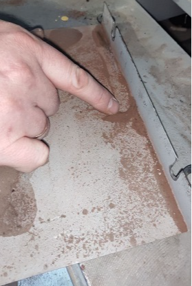
When removing the pallet of the fencing of the coupling joint, the presence of finely dispersed rust is striking, which may be the result of abrasion of metal on metal and further oxidation of particles.

In general, I strongly recommend that diagnostic specialists, in case of any suspicion of defects in the couplings, do not hesitate to look under the fences. Often there are both slides of a finely dispersed mixture of rubber and steel (with the destruction of bush-finger couplings) and pieces of rubber (with degradation of elastic cam couplings). It is also sometimes useful to inspect cam couplings with a stroboscope - the edges of a broken rubber sprocket will go beyond the dimensions of the coupling.
As expected, the abnormal noise was caused by the coupling.
On both couplings, an uneven end clearance was found in the area of the cams. Judging by such differences in the clearances, the problem is trivial - vertical misalignment, the motor shaft is below the pump shaft. The number of cams in each clutch is 6, which explains the 6th harmonic (in one revolution, each cam beats against the counterpart).
Interestingly, during the measurements, the driver told us that the couplings were replaced (removed from another pump). The reason is the same - extraneous noise, which remained. Therefore, they called the diagnosis. It is a pity that they did not pay attention to the alignment at all and did the extra work.
Without post factum analysis, the article would not be complete. Are we interested in the diagnostic signs of this defect? From the previous spectra, we found out - the presence of harmonic activity of the reverse frequency, the 6th harmonic in the direct spectrum of vibration velocity (and multiple harmonics) at low speeds, at high speeds, signs of misalignment (1-2 harmonics).
Now let's try to visualize the data obtained during measurements with the help of circular patterns of time signals of vibration velocity, vibration acceleration and envelope. This is instead of spectra, for better understanding.


From these data, the following conclusions can be drawn:
1. Impacts are more pronounced at low rpm.
2. With high dynamics, the collision processes become more unstable and their directions are mainly traced.
3. Under the conditions of overlapping frequencies on the resonance zones and the presence of other frequency components (electromagnetic and other defects), the circular vibration velocity diagrams are distorted (and, accordingly, diagnostics by spectra is difficult).
4. Vibration acceleration is also quite informative (provided there is a small high-frequency noise).
5. Diagnostics by envelopes looks the most preferable (which is logical). The envelopes are more pronounced in the direction of impact.
Note to the manufacturers of devices: it would be nice to make available the construction of circular diagrams in vibration analyzers, such visualization would greatly reduce the time for diagnostics at the place of operation.
Подскажите, что означают маркеры А1 и А2? это 1-я и 2-я гармоники? или?
Нет. На временном сигнале выбирается исследуемый период, при этом А1 - начало периода, А2 - его окончание. Перетаскивая А2 (то есть растягивая период по временному сигналу) мы наматываем "круги" на круглограмме. А2 не совпадает с А1 говорит лишь о том, что на круглограмме не целое количество оборотов. В общем не акцентируйте свое внимание на этих маркерах, это просто такая реализация в Condmaster Ruby.
Виталий, подскажите, какое количество намотанных кругов круглограммы вы бы хотели видеть на дисплее виброанализатора? возможно какой-то ряд? 5, 10, 15, 20? или 1, 5, 10. может быть ряд лучше делать не в кругах намотки а временной, типа 0,1с 0,25с 0,5с 1с 2с 4с? как бы Вам хотелось?
Если у Вас есть данные с такой же муфты, но уже сцентрованной, приведите пример, как выглядит круглограмма бездефектного соединения.