Alignment of the pump X 80-50-200
Расцентровка, Виброналадка, Вибродиагностика
The frequency of encounter with such a defect as misalignment depends on the culture of equipment installation and repair at your enterprise. On mine there are some problems with this, which makes my professional career more diverse. I propose to consider the classic practical case of misalignment and evaluate its effect on vibration parameters.
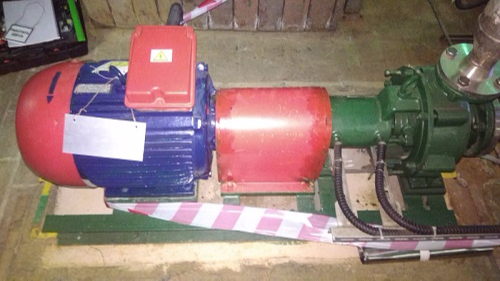
We have a centrifugal pump X 80-50-200, N = 15 kW, n = 2940 rpm. In accordance with ISO 10816-3, the vibration tolerance is 4.5 mm / s.
Vibration measurement data (RMS vibration velocity in the range of 10-1000 Hz):
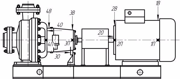
We fix the excess of permissible vibration values. We draw attention to the high levels of vertical and axial components. We note the large vibration load of bearings No. 2, 3 of the unit. To identify the defect, we perform an analysis of the spectra of vibration velocity.
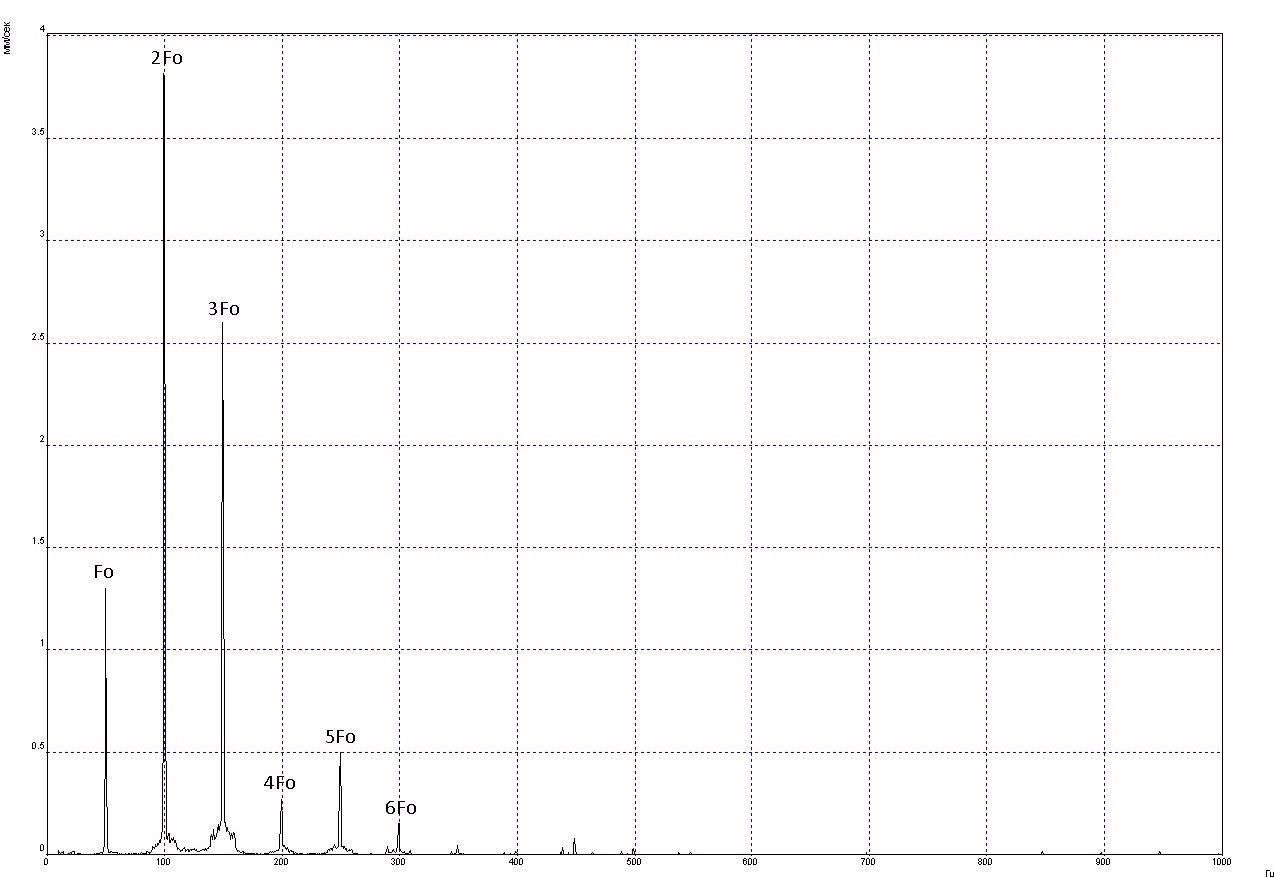
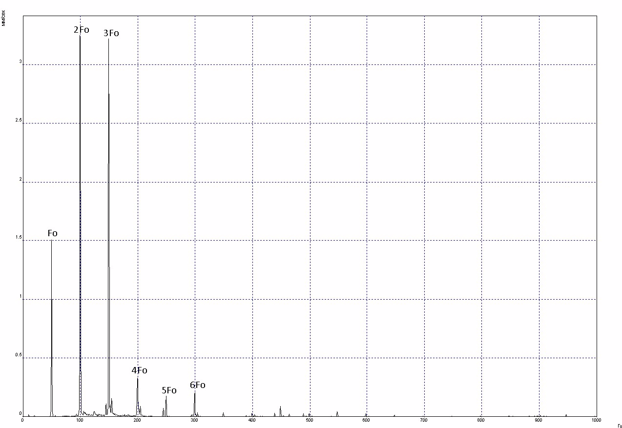
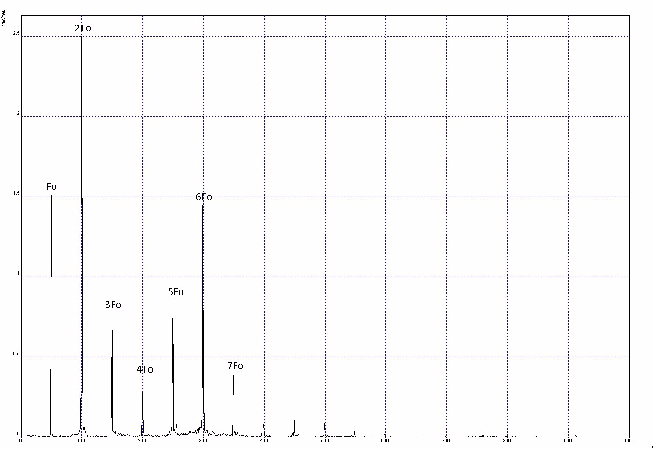
Fo - unit speed. Spetcras are saturated with harmonics of the reverse frequency. In the radial directions, we see the predominance of the second harmonic of the rotation frequency, in the axial direction, the third harmonic has a high amplitude. The data of the spectra and the general vibration velocity levels are very characteristic for the parallel alignment (bending) of the motor and pump coupling halves in the vertical direction and the angular (end) alignment of the coupling halves. In addition, the problem in the coupling connection indicates a large vibration load adjacent to the coupling of the bearing supports.
Now I propose to look at the spectra of the envelope of the vibration signal of the pump bearings.
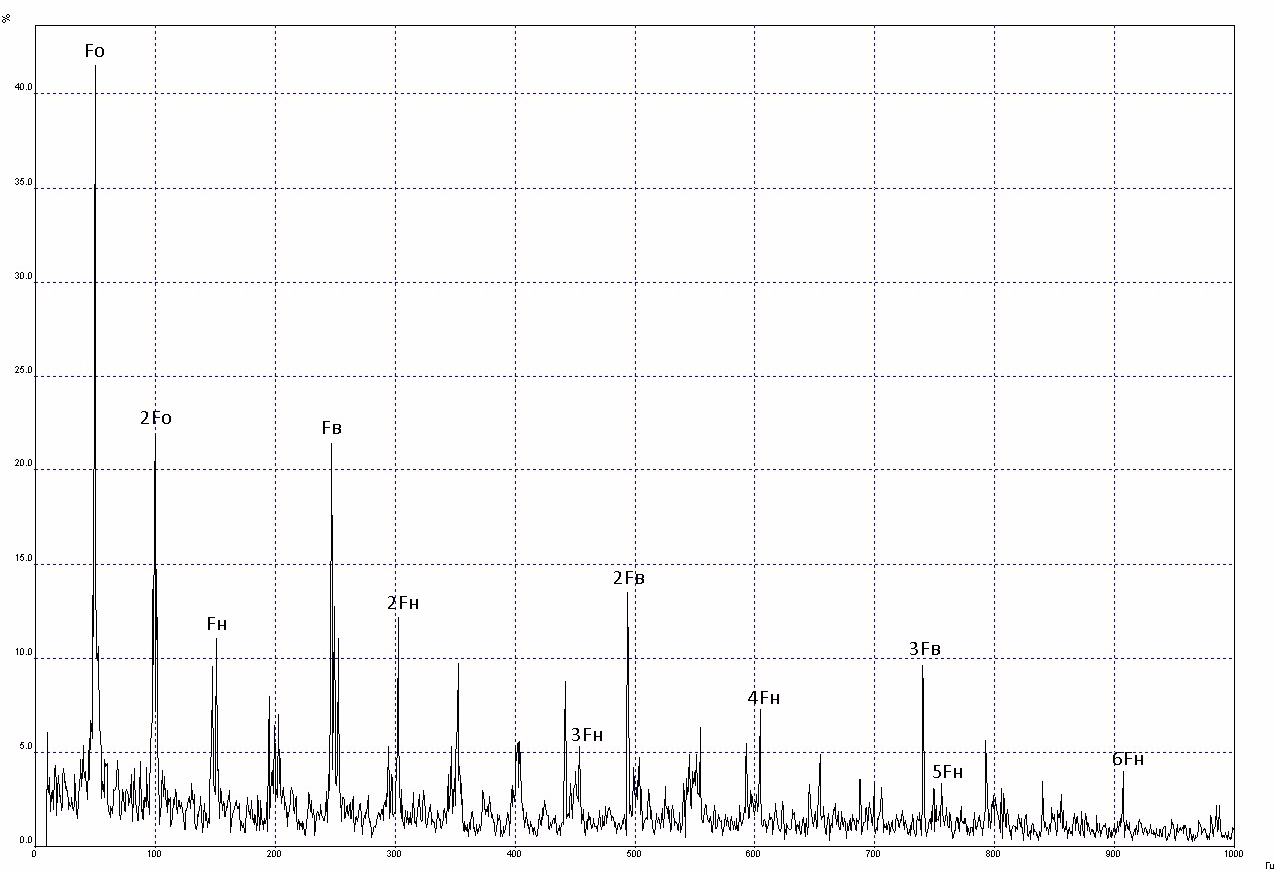
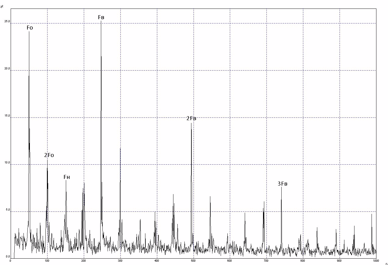
Fo - pump rotor speed, Fн - ball passing frequency of outer race, Fв - ball passing frequency of inner race. The bearings are located quite close and according to the amplitudes in the spectra, it can be assumed that the source of the spectral components of bearing No. 4 are problems in bearing No. 3. Since it is assumed that there is a strong alignment, it can be concluded that high levels of Fo are associated with a strong rolling around of the rotor in bearing No. 3, the components Fн and Fв are the result of this rolling-in - the rolling bodies move along the tracks of the outer and inner rings with great effort and friction. Therefore, we are not in a hurry to defect bearing No. 3.
Spectrum diagnostics are good, but I want to be more confident in the presence of misalignment. Measuring the phases of vibration adjacent to the coupling of the supports and analyzing their relationships is a very practical and reliable way to determine the alignment, but more time-consuming. And taking into account the fact that there was no RPM sensor at hand, and, accordingly, the possibility of measuring phases, I use a simpler method, which I often use - a visual inspection. Experience has shown that flexible sleeve-finger couplings compensate fairly well for a small misalignment. But the center-line, leading to high levels of vibration, is visually visible well, often it is not even necessary to apply a ruler. So it happened this time. Having removed the guard (do not forget about safety measures - the equipment must be de-energized), it became apparent that there is an alignment in the vertical direction - the motor coupling half is 1-2 mm higher than the pump coupling half.
Next, a protocol is drawn up with all the justifications and the recommendation to center the pump unit. After some time, I found out that the pump was never centered (I won’t take a look at the reason). Since defects must be closed (and moral satisfaction), he offered his services to the owner of the equipment, to which he gladly agreed.
Alignment measurement data:
Vertical - Parallel = 0.54 mm
- angular = 0.10 mm
Horizontal - Parallel = 0.18 mm
- angular = 0.28 mm
Tolerance 0.06 mm.
With a colleague, with the help of a laser centering, it was possible to quickly and accurately perform this work:
Vertical - Parallel = 0.02 mm
- angular = 0.02 mm
Horizontal - Parallel = 0.03 mm
- angular = 0.01 mm
Tolerance 0.06 mm.
Measuring vibration after centering:
They achieved acceptable results in terms of vibration velocity.
This practical example showed the effect of strong alignment on the vibration parameters of the unit. I'd like to evaluate the impact of the alignment on the parameters of electricity consumption. For this, before alignment, the values of the active power of the electric motor were measured. As the opportunity arises, I will measure the active power after alignment with the same technological parameters. Comparison of power before and after alignment will make it possible to confirm or refute the data of some marketers, who claim that when the alignment is made, the consumed electricity increases by 10-15%. Believe it weakly, but I think it will be interesting to all of us to check it.