Resonant fan design
This article discusses another defect in the design / installation of the fan, which led to increased vibration. We determine the cause and find a solution to the problem.
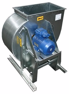
Invited to the fan to look for extraneous noise from him. The source was the contact of the vibrating snail on the bearing shield of the electric motor, they quickly dealt with this. But when measuring vibration, they found its increased level (> 4.5 mm / s).
Measurement data (RMS vibration velocity in the range of 10-1000 Hz):
Spectrum of vibration velocity in the horizontal direction:
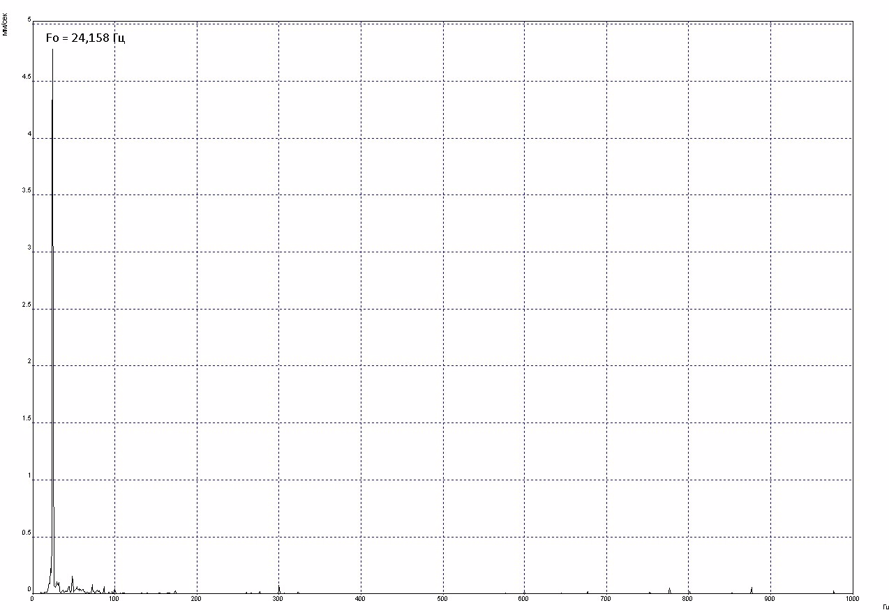
As you can see, the vibration at the reverse frequency of 24.2 Hz. A sufficiently large difference in amplitudes in the vertical and horizontal directions may indicate a greater contribution of resonance than imbalance. Check for resonance. I give the command to turn off the unit, and at this time in the mode without averaging I observe the vibration amplitude on the coast. Immediately after a shutdown, the amplitude of the vibration velocity increases to 11 mm / s and drops sharply to 1.6 mm / s, then another increase and a sharp drop. It is very likely that we are in the field of resonance. Waiting for the end of the run, I often measure my own with a shock test.
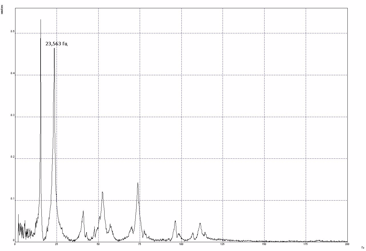
The spectrum of natural frequencies confirms that at the nominal frequency of rotation we are in the resonance region, one more peak is also visible in the region of 15 Hz, which we always pass during acceleration-coast.
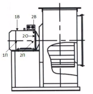
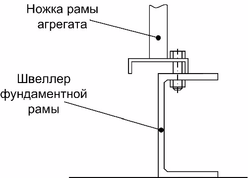
Inspecting the mounting of the unit frame, I see a design or installation defect. The channel base to which the fan frame should be attached does not match the size of the frame. At the same time, the supporting part of the fan frame is made of a U-shaped profile, and the fit to the base should be the “legs” of this profile. Due to the size mismatch, the U-shaped profile was located on the channel with only one of its sides, which reduced the rigidity of the entire structure.
In this regard, an additional support was simply suggested for the part of the frame hanging in the air. It was decided to use an imitation of a jack in the form of a stud with nuts screwed on its ends.
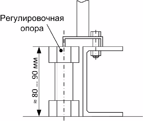
I turn on the device in the measurement mode without averaging and adjust the position of the nut on the stud. At the initial moment, a sharp increase in vibration occurs up to 18 mm / s, the entire fan design begins to rattle. This is logical, increasing the stiffness, we shift the natural frequency towards the reverse and with their full coincidence we get the maximum vibration. The main thing here is not to be afraid and without stopping at the peak of the resonance to continue to increase the stiffness, the task is to jump over the natural frequency through the reverse and take it as far as possible. As a result, no more than 5 revolutions were made with a nut, and the vibration dropped significantly.
Vibration data after installation and adjustment of the additional support:
Leaving the jacks behind is a bad tone, therefore, in the protocol the equipment owner indicated that the vibration adjustment will be completed after installing additional support under the frame in the form of a corner.
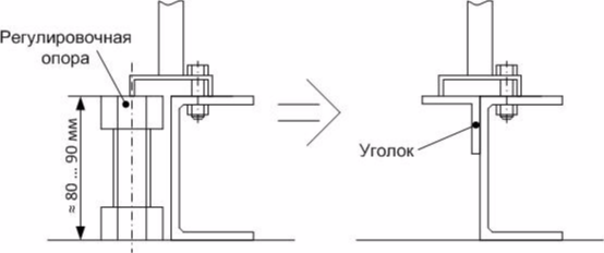
At the same time, fixing the corner (bolt connection or welding) is carried out under my control, since it is necessary to provide the required rigidity.