Elimination of resonance on a fan type VRAN 9
Виброналадка, Вибродиагностика, Резонанс
The fight against vibration of fans is a special niche in the practice of vibration diagnostics. In many enterprises, fans turn a blind eye - they say cheap, low-liability, etc. But in my opinion, fans are the main source of experience for a beginner vibration diagnostics / vibration adjuster. Fans, as a rule, are mounted / operated in violation of the requirements, have low rigidity, and accordingly a huge mass of defects is manifested on them. In this article, we consider the effect of improper installation on the vibration of the unit, we localize the defect and eliminate it.
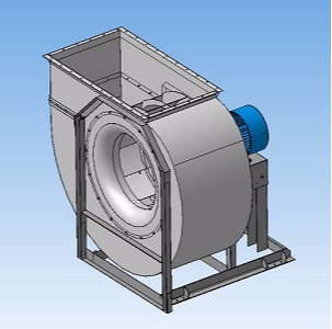
Another call for diagnosis. The reason is high vibration, which leads to the loss of rivets from the fan coil (N = 15 kW, n = 750 rpm).
RMS measurement data of vibration velocity in the range of 10-1000 Hz:
Vibration tolerance of 4.5 mm / s. From the table we see a big difference between the vertical and horizontal components, so with a high degree of probability we can assume the presence of resonance in the horizontal direction.
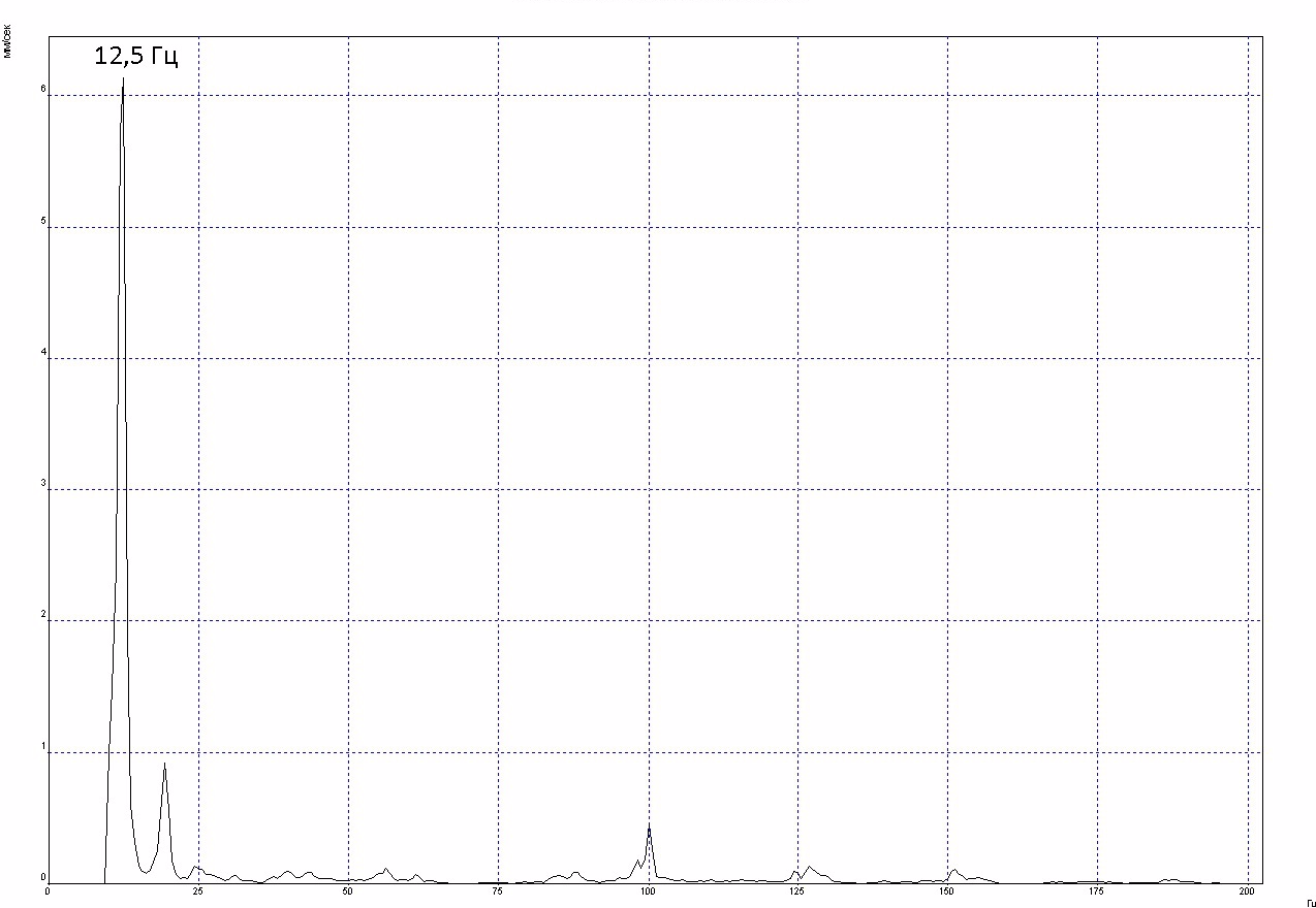
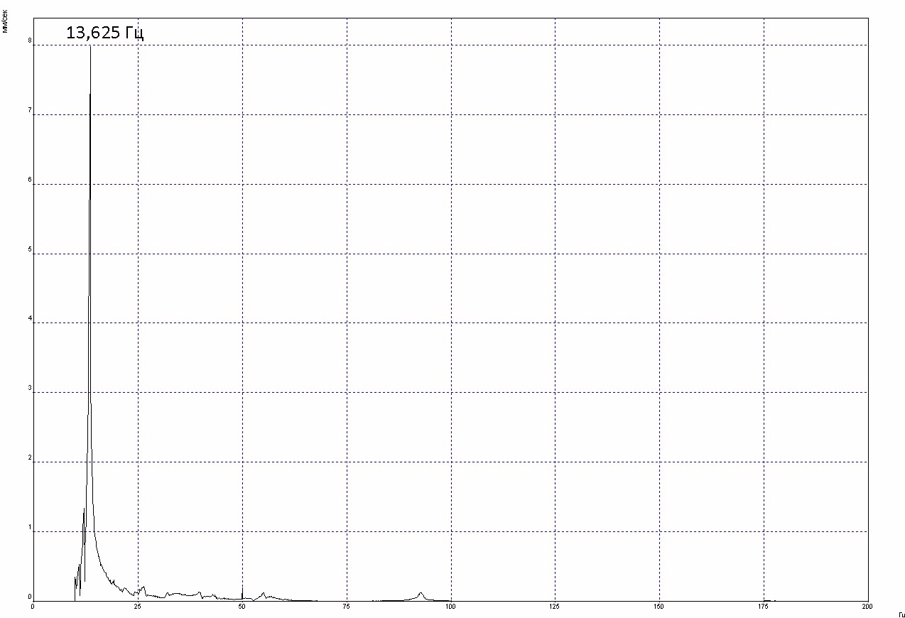
Spectrum of vibration velocity in the horizontal direction:
In the axial direction:
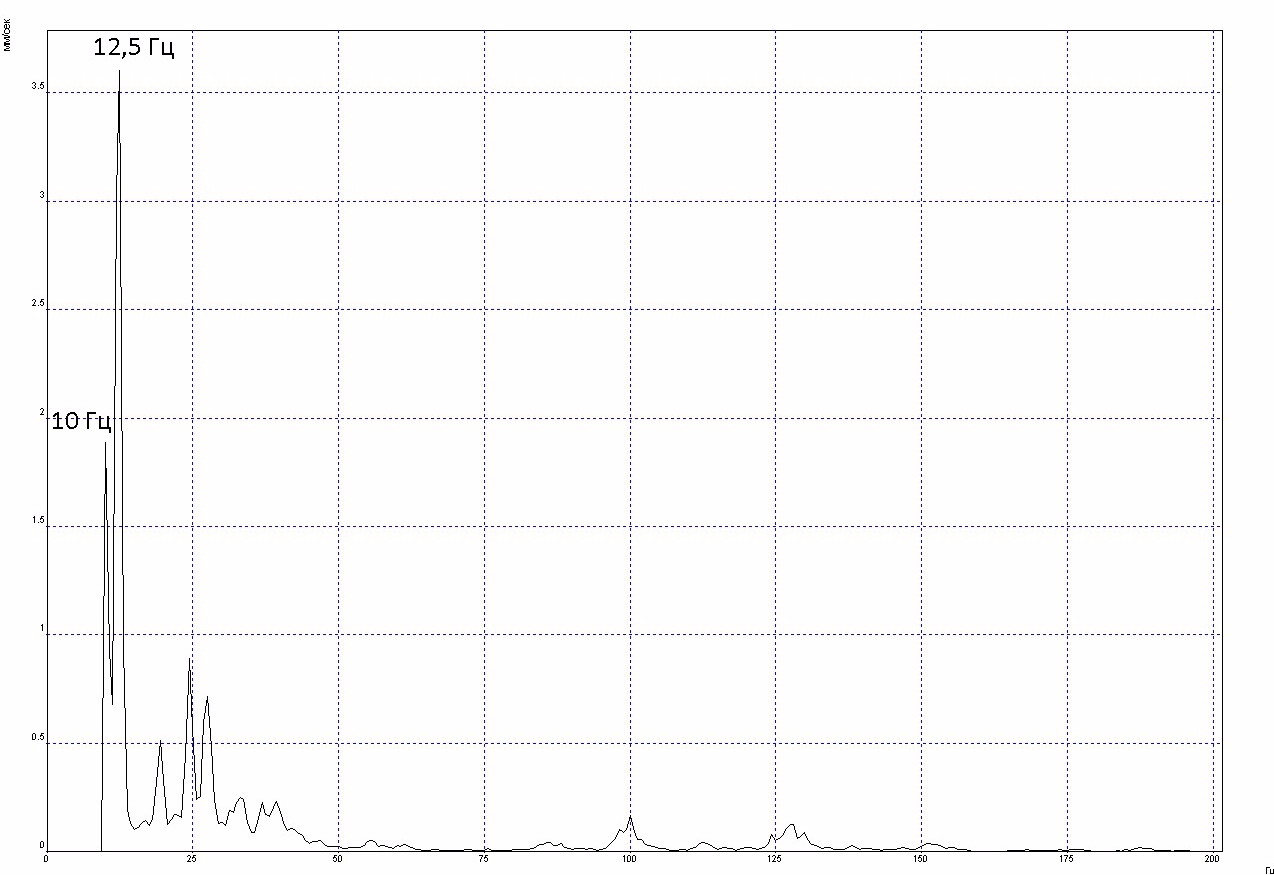
As you can see, the vibration is concentrated at the reverse frequency. We stop the unit and determine the natural frequencies with a shock test:
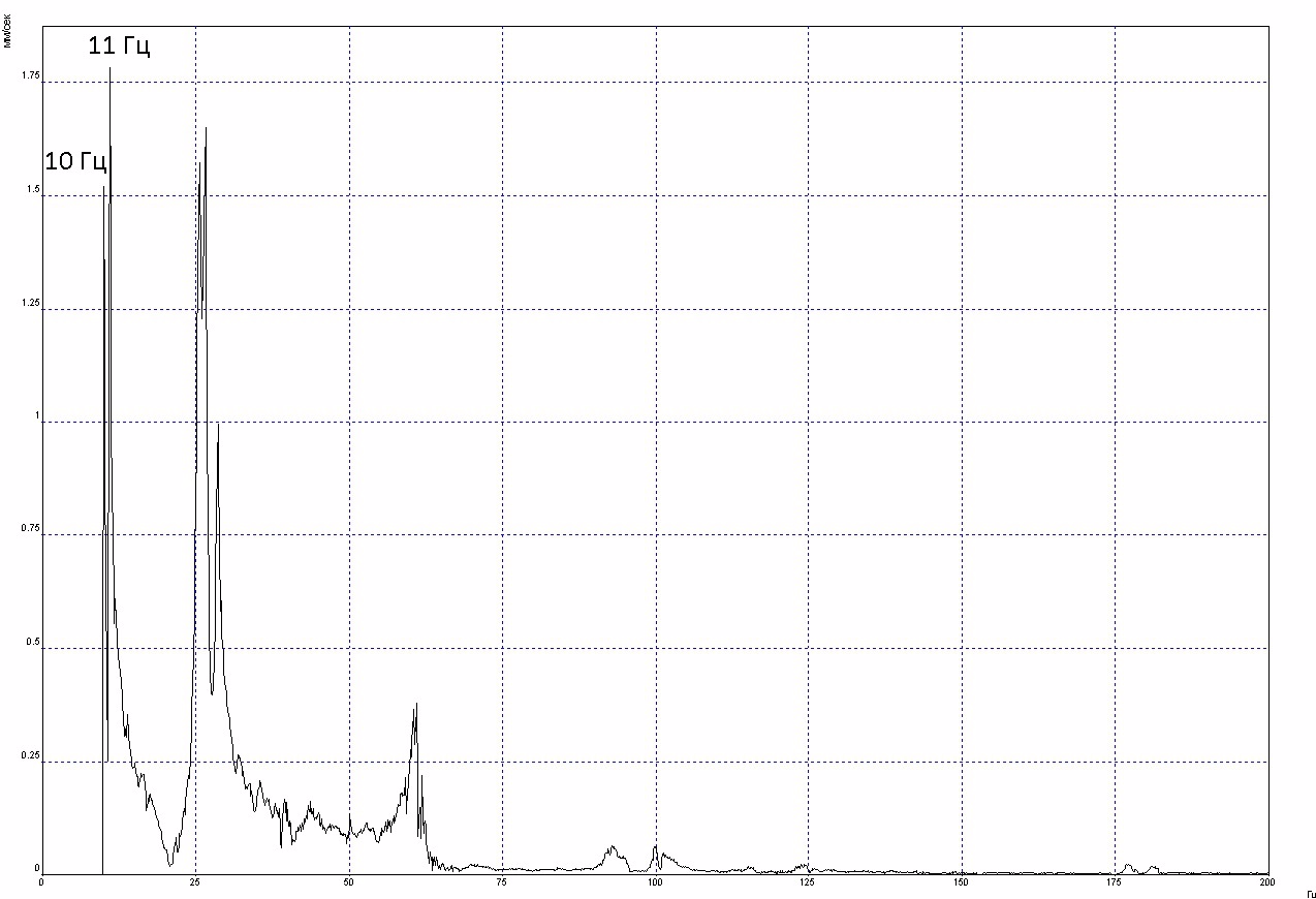
The rotation frequency of 12.5 Hz is located in the region of natural frequencies. Resonance is confirmed. Now the main question is how to get rid of it? From theory, we know that eigenfrequencies can be removed by changing the mass or stiffness. Of course, we will not mount the box with the fraction, the option with changing the mass disappears. Only stiffness remains.
When removing resonances, I have a principled approach. First you need to inspect the quality of installation of the equipment (tightening fasteners, full fit of mating parts, the absence of loosening of anchors, etc.). Then experimentally determine the place where the change in stiffness characteristics most effectively reduces the effect of resonance on vibration. For this, improvised materials are used - scrap, pipe, jack, etc. And only then, when the place is determined, it is possible to make changes in the design - add fasteners, weld stiffeners, secure the fit by laying plates, etc. I have already seen enough in my own experience how stiff ribs are thoughtlessly welded at random. Often, this not only does not improve the vibration state, but on the contrary worsens it, leads to the curvature of the frames, spoils the aesthetic appearance of the unit design.
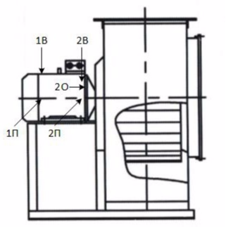
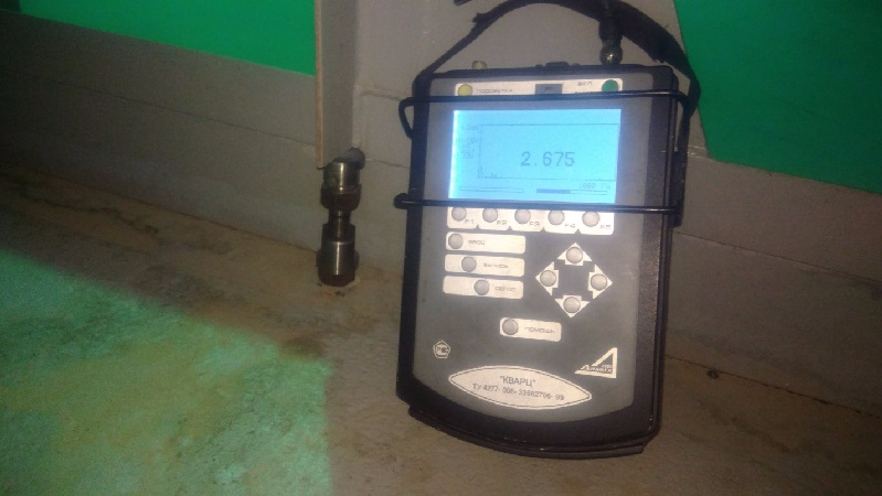
Inspection of the unit showed the lack of abutment of the unit frame to the channel of the base directly under the pillar of the electric motor stand from the side of bearing No. 2. It is determined easily - we press a finger to the junction of two surfaces. For some reason, fasteners are provided only at the four corners of the unit frame. Judging by the spectra, the natural frequency must be taken away from the circulating frequency in the direction of its increase, that is, to increase the stiffness. And here its amplification just begs. Now we check this assumption by installing and adjusting the jack under this rack, looking at the readings in the mode without averaging (the sensor is installed at point 2П):
We measure the SKZ vibration velocity at all points after installing the jack:
Next, a protocol is drawn up indicating the reasons for the increased vibration and recommendations for detuning from resonance. As a result, the owner of the equipment gives the green light to the elimination of vibration. Two options for solving the problem are being asked - to drill the frame and the channel with the subsequent installation of fasteners, or to ensure fit by installing the plates in the gap between the frame and the channel. I have chosen the second option, as the easiest. In the specified gap, a 2 mm thick plate was hammered under vibration control on a running unit. Visually it is not visible, which is more than happy with everything. And the final RMS measurement of vibration velocity after such a vibration adjustment:
Fast, cheap, efficient.
В какие места нужно ставить датчики и в какие бить, чтобы правильно определить резонанс?
При резонансе ставьте датчик в точку с максимальной вибрацией. Конструкцию старайтесь возбуждать в этом же направлении/плоскости, так как здесь важно вызвать колебания по проблемной форме/моде. Удар производим на некотором удалении от акселерометра. Если мы говорим об обычном тесте на удар (без использования ударного молотка с тензодатчиком), то для возбуждения собственных частот можно использовать подручные средства. Для объектов с небольшой жесткостью достаточно удара кулаком, более жесткие конструкции иногда удобнее возбуждать с ноги или массивным бревном (без шуток). Были случаи когда приходилось прыгать на большом жестком оборудовании (корпус циркнасоса, электродвигатель 7 МВт). Здесь важно каждый удар наносить плотно, четко и один раз, случайный двойной-тройной удар из-за отскока бьющего элемента испортит весь сигнал. При этом незабудьте оптимально настроить порог срабатывания в настройках прибора, иначе можете отбить себе руки/ноги/молоток.
На полученном спектре помимо собственных частот вы можете увидеть частоты наведенной вибрации от рядом работающего оборудования. Как отличить? Собственные частоты как правило имеют уширения в своем основании, в то время как наведенные проявляются в виде острых пиков. В большинстве случаев вы увидете на одном спектре несколько собственных частот. Каждая частота соответствует своей форме/моде колебаний. Формы колебаний на низких частотах самые простые, изгибные (как тростник на ветру), на высоких частотах (>200 Гц) сложные, изгибно-крутильные. Конечно по спектрам мы не увидим форму колебаний при резонансе, но по значениям СКЗ вибрации (а тем более если есть данные фазы) простейшие формы можно легко себе представить. Зная форму колебаний можно поискать подходящее место для их ограничения, что должно привести к смещению проблемной собственной частоты в спектре.
Зачастую, определенная тестом на удар собственная частота может не совпадать с оборотной на 1-5 Гц, что может вызвать сомнения в наличии резонанса. Или наоборот, собственная частота может отстоять от оборотной всего на 0,5 Гц и специалист может прийти к выводу о наличии резонанса при его отсутствии. В связи с этим резонанс желательно подтвердить экспериментально на работающем оборудовании. Если конструкция не слишком жесткая, то достаточно надавить на нее, поджать ломиком в каких-то местах, встать на нее используя свою массу и т.п. Если достаточно жесткая и силовым путем жесткость не изменить, то можно покрутить крепления к раме/фундаменту с целью их ослабления. Все эти манипуляции надо делать параллельно с измерением вибрации. Любое ее существенное изменение (падение или рост) подтвердит наличие резонанса. Дальше уже можно спокойно поразмышлять каким образом оптимальнее выполнить отстройку собственных частот.
Ой сколько я настрочил.
спасибо за развернутый ответ