Putting modal analysis into practice
Резонанс, Вибродиагностика, Модальный анализ
I want to devote this article to the practical application of modal analysis. I have never dealt with modal analysis, there were no devices with corresponding functions, and now they are not and are not expected. Very expensive. But this is not a reason to despair and put an end to such an interesting method. The solution to the problem is 3D modeling and calculation of vibration modes. How I came to this, how to do it and what I got in the end - read on.
Description of the problem
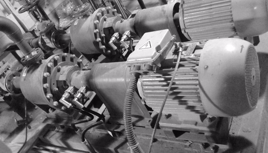
We have 4 centrifugal pumps with electric motors N = 37 kW, n = 3000 rpm. Three of them have a problem with increased vibration of electric motors. Vibration is high both at idle and complete with pumps.
Initial data
To illustrate the problem, we take the scroll data of one of the electric motors idling at the place of operation.
RMS of vibration velocity in the range of 10-1000 Hz, mm / s:
Spectra of vibration velocity at all control points:
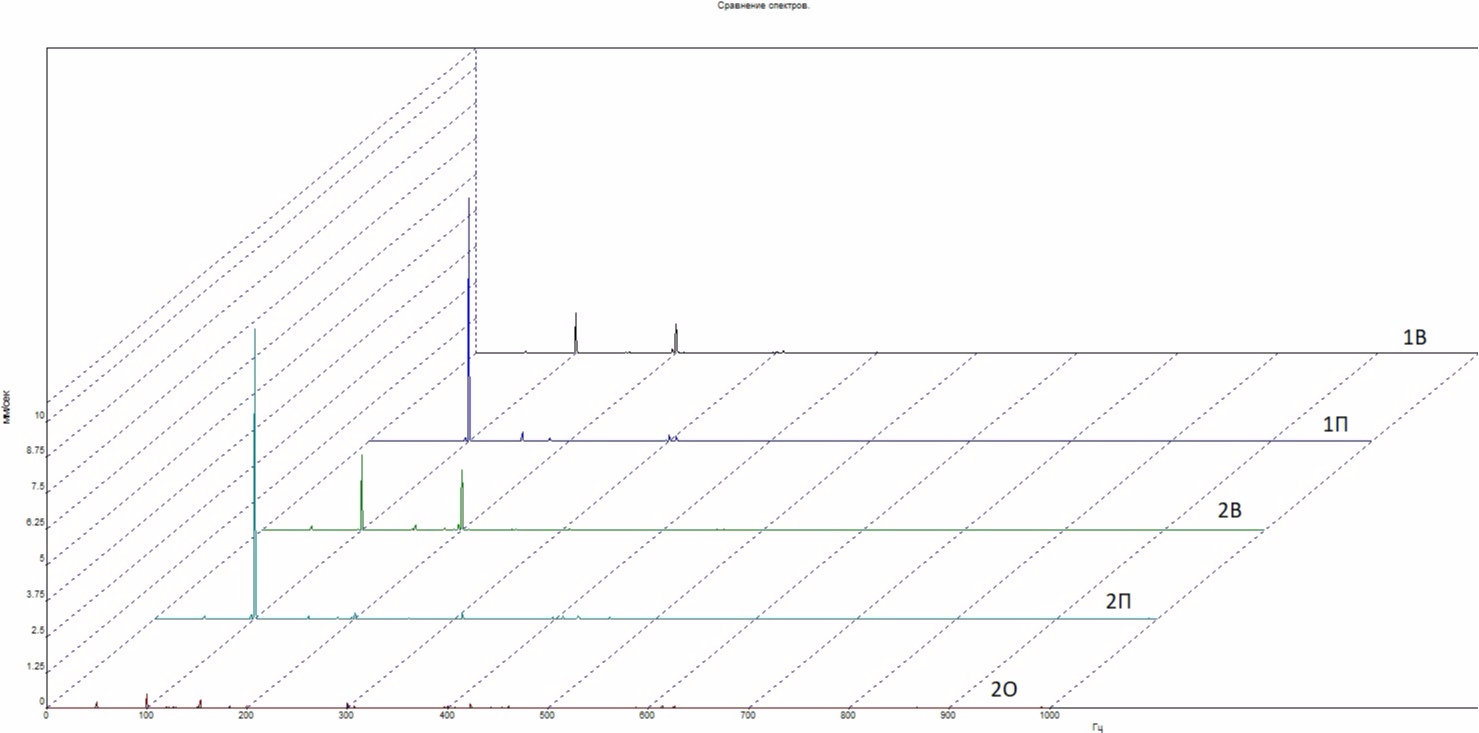
The component dominates in the spectra is 100.0 Hz; in the vertical direction, 200.0 Hz is also noticeable. The operation of the electric motor is accompanied by a strong hum.
Analysis
Weaken fastenings of paws of the electric motor:
The rumble stopped. The situation is very similar to such a defect as a soft paw. But on similar electric motors, they tried to eliminate the soft paw - scribbled the frame to level the surfaces under the paws. The problem of increased vibration has not been resolved. From my own experience, I can say that the soft paw in the vast majority of cases does not cause very high levels of vibration.
When tightening the soft paw, we bend the body, which changes the gap between the rotor and the stator of the electric motor and distorts the electromagnetic field, causing vibration at a double frequency of the network 100 Hz. Therefore, we see almost 100 Hz in the transverse (horizontal) direction on almost all electric motors in direct spectra. But we achieve high vibrational activity at resonance. By weakening the fastening of the paw, we only decrease the stiffness, which changes the natural frequency and weakens / eliminates the resonance. And at this point, many vibrodiagnostics are confused, believing that if, when the feet of the electric motor are loosened, the vibration drops, then this defect is nothing more than a soft paw. An inaccurate diagnosis leads to useless time-consuming work (scraping the frame or engine legs).
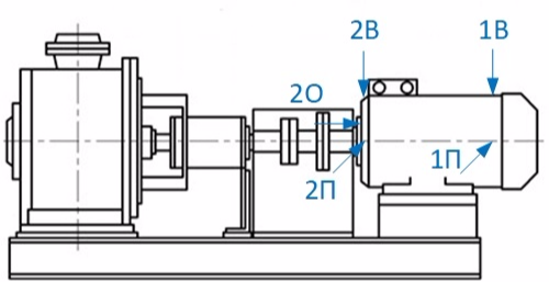
A shock test determines the natural frequencies in the transverse direction (at point 2П):
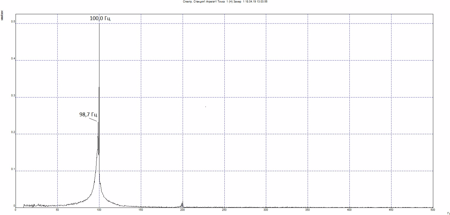
The peak at 100.0 Hz is very narrow and is probably due to induced vibration. But a wide peak with a maximum of 98.7 Hz is the natural frequency in the transverse direction. Resonance is confirmed.
Additionally, we determine the natural frequency in the axial direction (at point 2O):
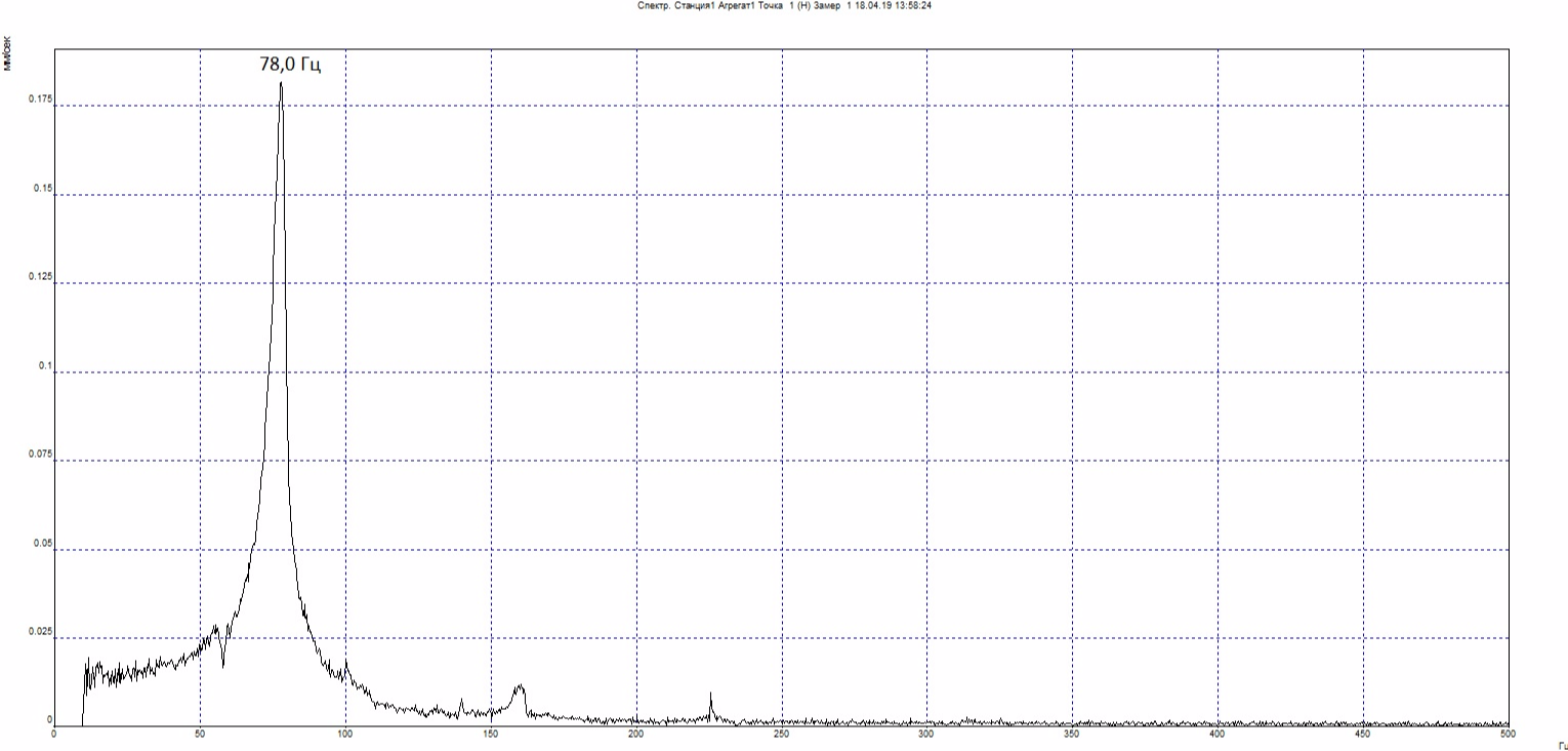
Remember the natural frequency of 78.0 Hz, it will come in handy later.
In the vertical direction, the test did not start with a blow - the ribbed surface and the box hinder the normal performance of this operation.
Total, we have a resonance.
Temporary solution
Further, the owner of the equipment gave the command to joint the coupling and perform scrolling of the assembly. The result remained the same - increased vibration in the transverse direction. This time, I did not agree to loosen the paw mount and suggested to strengthen the channel of the frame under the electric motor with homemade jacks (studs with nuts at the ends) to detune from the resonance. Vibration decreased to 3-4 mm / s, in this state everything remains to this day.
Modal analysis
As you know, such a solution does not suit me. It is necessary to find the root cause of the resonance. As I wrote above, one of the four pumps worked without any complaints about vibration. Visually, all pumps and their foundations look the same.
Since I am sure that the problem is structural in nature, it would be nice to see the oscillation mode at a frequency of 100.0 Hz to identify the cause. Quartz / Topaz devices naturally lack such functionality. But after all, designers somehow carry out the calculation of structures, mechanisms and components at natural frequencies. Somewhere on the Internet I saw beautiful pictures with calculations of waveforms in different CAD systems. I am sure that this is somewhat easier than building a rocket, and for self-education it would not hurt to try to simulate your problem.
Once at the institute I was not bad at drawing in Compass-3D. And it turned out that APM FEM module, an application for performing express calculations of solid objects and visualizing the results of these calculations, was already brought into this wonderful program. We try.
Source data collection
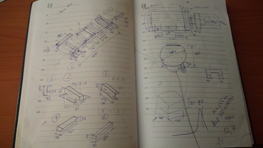
Since the task is to perform the calculation as accurately as possible, to build a 3D model, the real dimensions of the frame and electric motor are required. Perform removal of geometric dimensions:
3D model creation
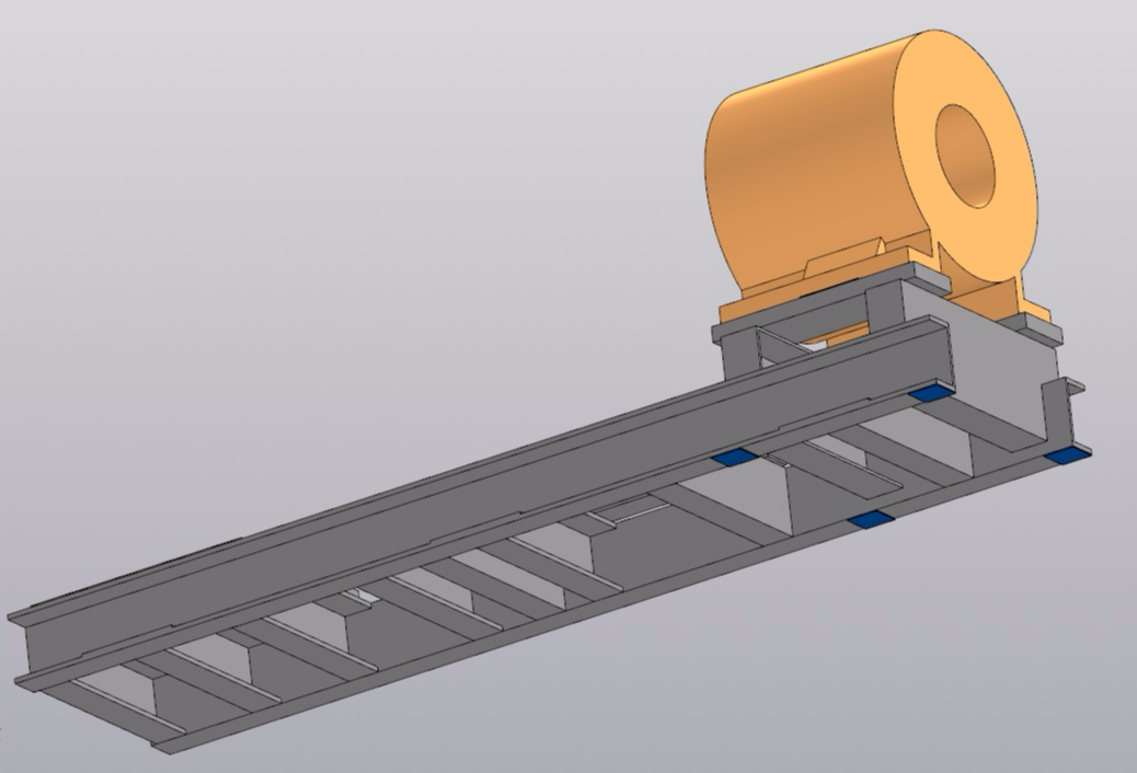
In Compass-3D, in geometric dimensions, I build a 3D model:
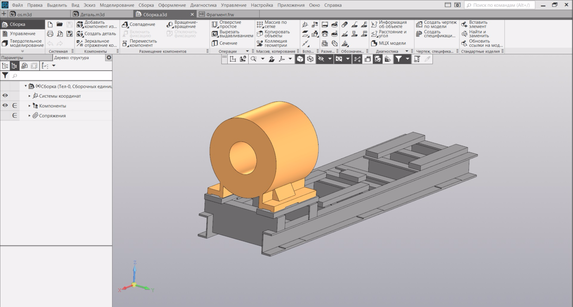
To fully draw the electric motor - very time-consuming. Therefore, I accurately draw its paws, and replace the case with a cylinder. In this case, I select the inner diameter of the cylinder so that in the model the mass of the electric motor is equal to the nameplate. The pump is located at the other end of the frame and is unlikely to affect the natural frequencies of the electric motor, so we can do without it.
Calculation in APM FEM
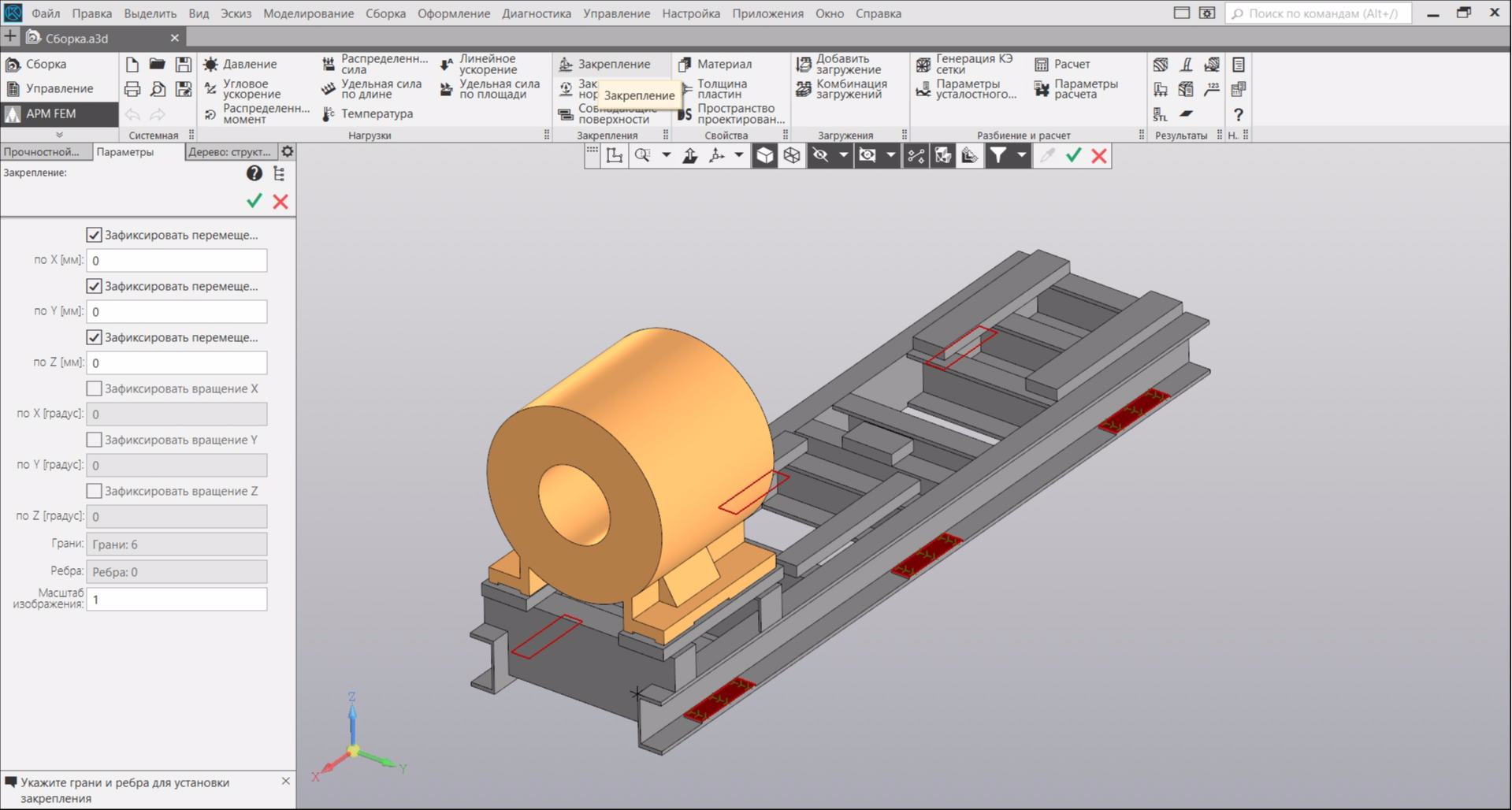
Next, in the APM FEM application, we select the frame fixing places - the platforms to which the nuts of the foundation anchors are pressed:
We proceed to the generation of a finite element mesh (FE mesh). I selected the grid options shown in the figure below. Reducing the size of the elements and complicating their shape will increase the accuracy of the calculation, but further increase the time and memory consumption.
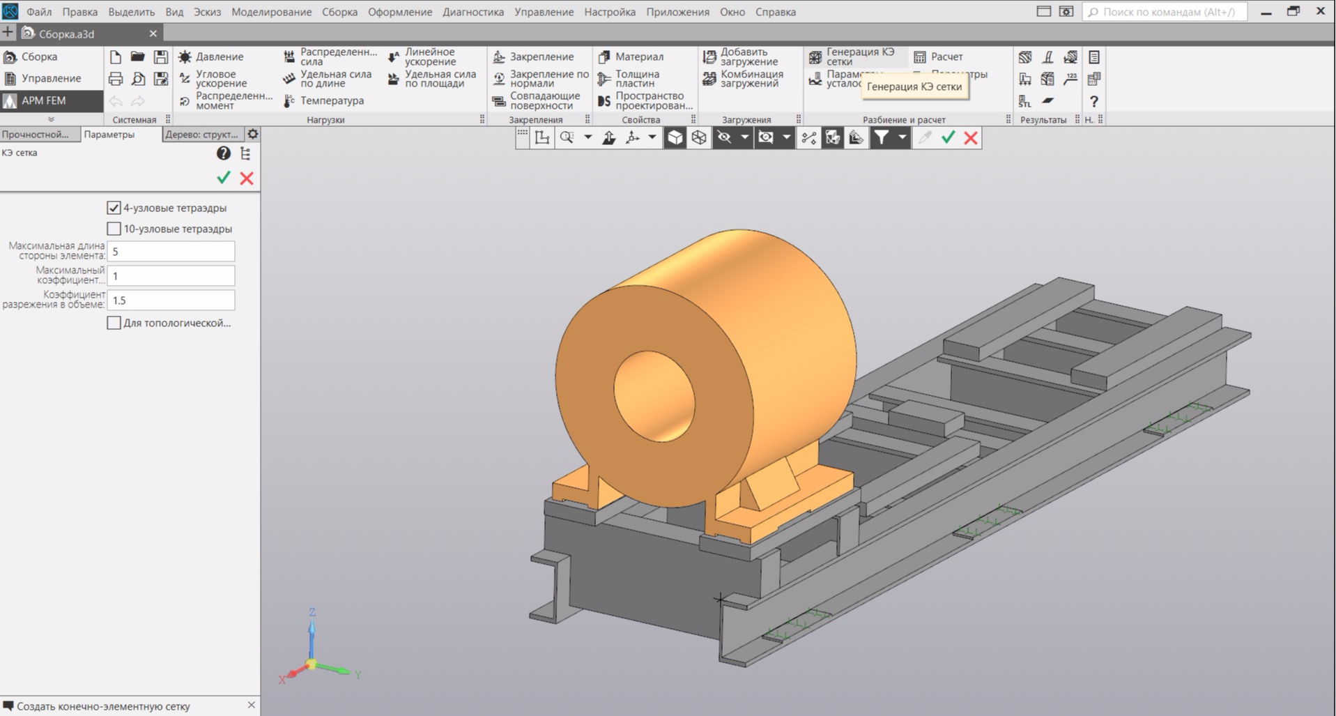
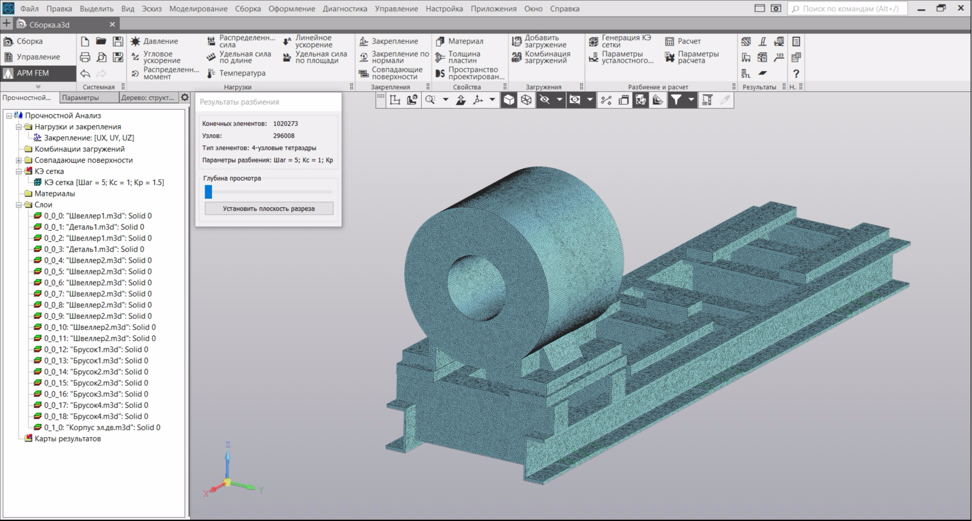
If you did not specify the material of the model elements - it does not matter. The program itself will offer you to assign steel as a material for all elements. At the end of the generation, your model will look like a grid of elements. In my case, the model began to consist of just over 1 million finite elements:
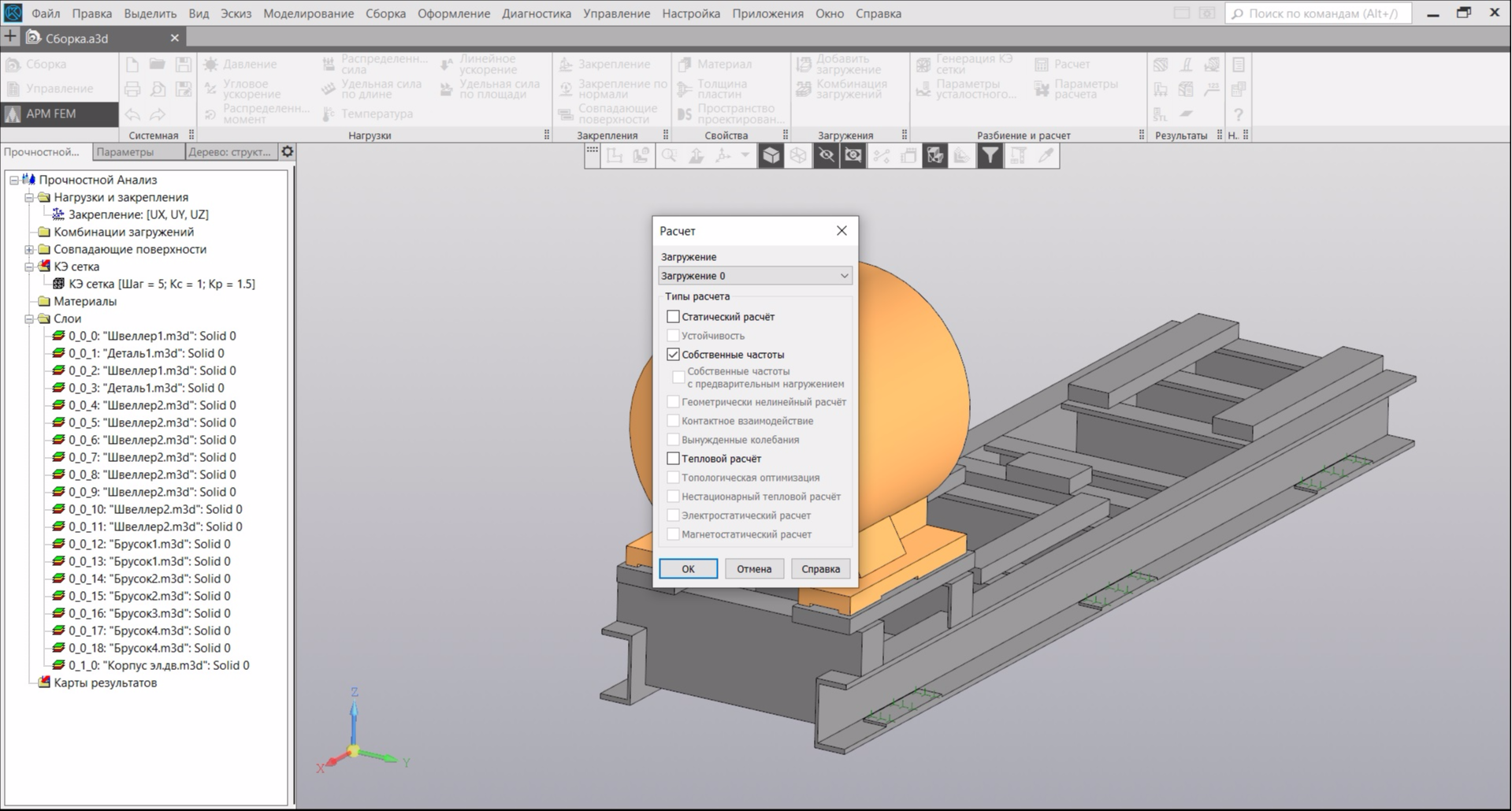
Next, in the panel, click the "Calculation" button and in the dialog box select the item "Natural frequencies":
You can go drink coffee, as the calculation, depending on the selected parameters of the FE grid, takes a lot of time. At the end of the calculation, click on the “Results Map” icon and open the “Frequency” combo box. The program will give us a table with the first five calculated natural frequencies:
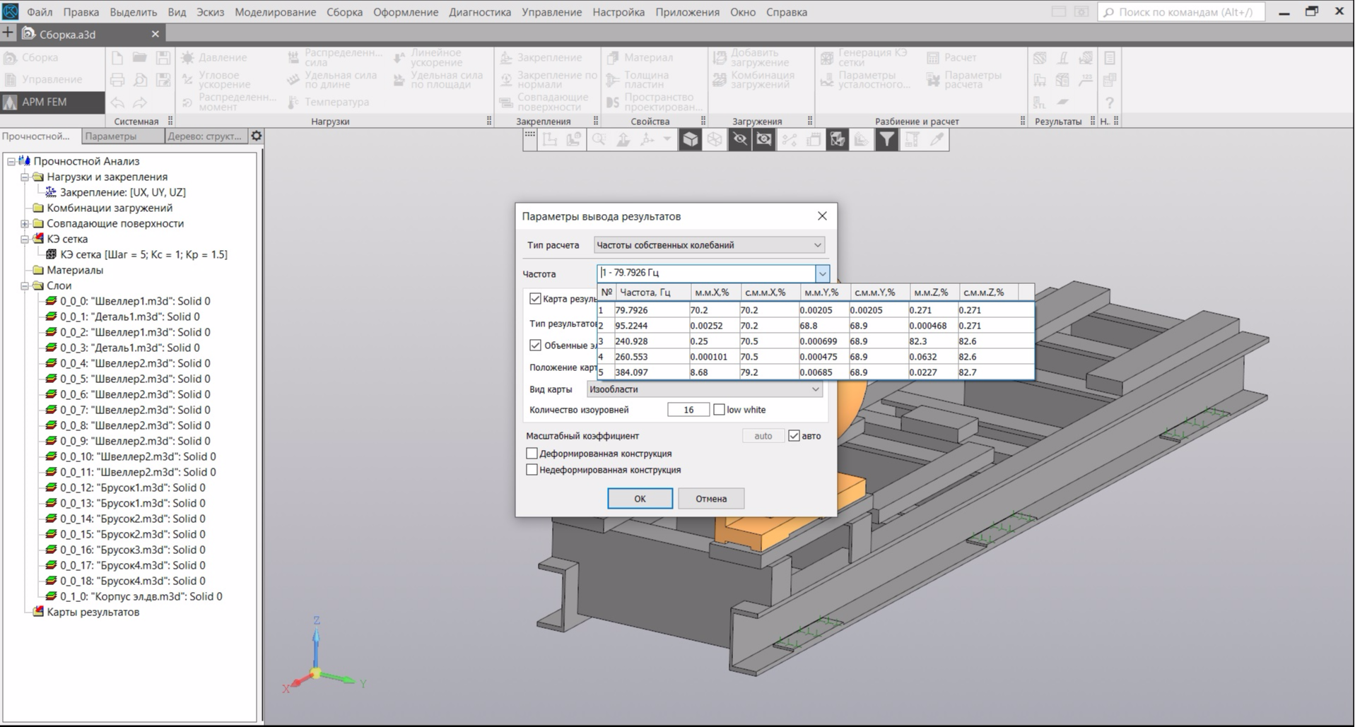
But we are still interested in the direction of the vibration modes. Therefore, we select the second line in the table and click "OK." The first two vibration modes will appear in the results map (the rest are not interesting to us), when selected, their visual picture will be displayed:
On the left is the first mode of oscillations at a frequency of 79.79 Hz. The axial direction of vibrations is guessed. The real natural frequency in the axial direction was 78 Hz. On the right is the second mode of oscillations at a frequency of 95.22 Hz. Very similar to the horizontal direction of oscillation. Our real natural frequency was 98.7 Hz.
Real and calculated data we agree with a slight error. But with the forms of vibrations it is not very clear. Therefore, there was a desire to use the world-renowned design tool - ANSYS. I have never worked with this program and now there is a reason.
Calculation in ANSYS
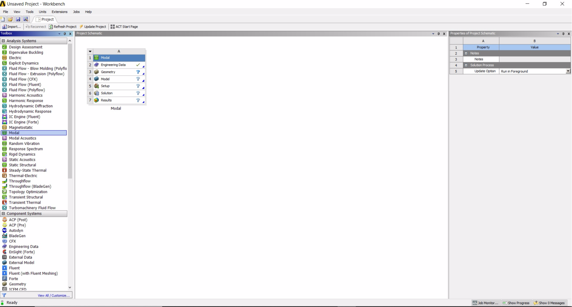
I have no desire to draw the model again, so in Compass-3D I save the existing model in the common .igs format for both CAD programs. Next, open the ANSYS Workbench. In the toolbar (left side of the window) we find the "Modal" analysis system and drag it onto the project diagram (in the central part of the interface). A sign will appear on the diagram:
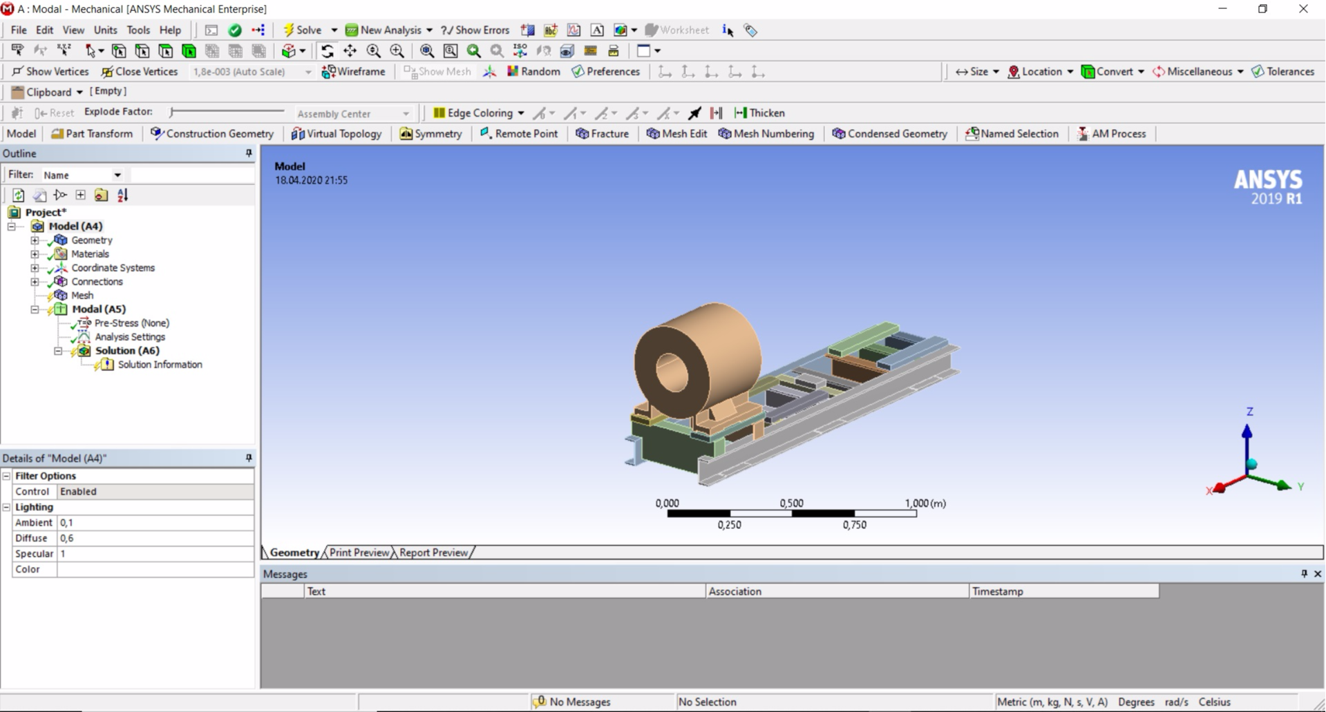
We do not touch the first row of the "Modal" table. The second line "Engineering Data" is used to select materials, by default only one material is selected for all elements of the model - steel. This material completely suits us, but if necessary, by right-clicking on this line and selecting "Edit ..." we can proceed to add other materials to the set. The third line, "Geometry", is used to add model geometry to the project. Right-click and in the menu that appears, go to "Import Geometry" → "Browse ..." and select the previously saved file in .igs format. And finally, the fourth row of the "Model" table that interests us. Right-click and select "Edit ...". The ANSYS Mechanical program will start, in which we will have to continue working. Our 3D model will load automatically:
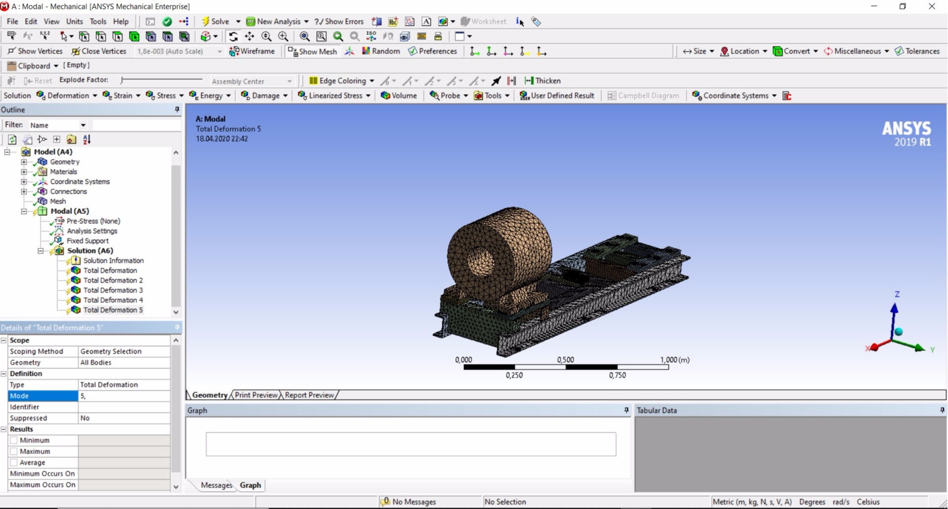
Next, you need to make a few settings. First of all, we need to add places for fixing the frame. In the project tree, right-click on "Analysis Settings", then "Insert" → "Fixed Support" and on the model we select the places where the anchor nuts touch the frame. After selecting the fastening surfaces in the lower left corner of the screen, click "Apply".
Then you need to create a finite element mesh. In the project tree, select "Mesh" and below in the settings panel, open the "Sizing" list, find and edit the line "Resolution". Select a value of 4. This value affects the number of elements in the grid. Those who have a lot of RAM can try to choose higher values. Next, right-click "Mesh" → "Generate Mesh". Our model is covered with the necessary mesh.
Now we need to set the number of vibration modes that we need to calculate. Let's say that we are interested in the first five modes. In the project tree, select "Analysis Settings" and in the settings panel below "Options" → "Max Modes to Find" set the value to 5. Then, in the project tree, right-click on "Solution (A6)" and select "Insert" → "Deformation "→" Total ". The “Total Deformation” component will appear in the “Solution (A6)” branch. We perform this procedure 5 times. The components of the calculation of vibrational modes will go to these components. Each component of "Total Deformation" must be assigned its own mode of vibration. Select "Total Deformation 2" and in the settings panel below find "Definition" → "Mode" and set the value to 2. For "Total Deformation 3" set the value to 3 and so on.
All settings are completed and to perform the calculation, press the F5 key. The calculation will require a certain amount of time and you can go have a drink of coffee. The calculation results will be presented in the panels below (under the 3D model):
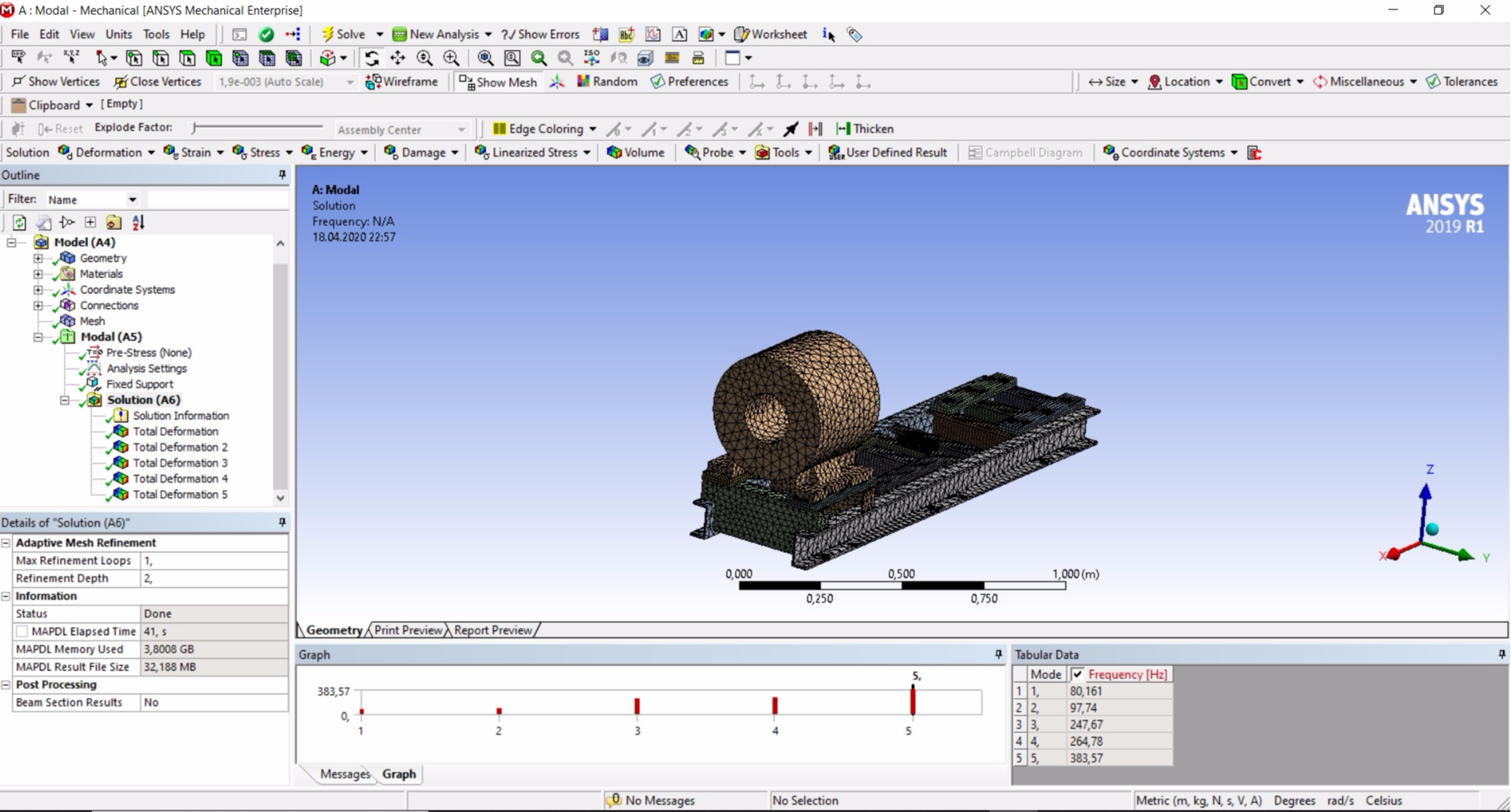
The first mode of oscillations at a frequency of 80.161 Hz, the second mode - 97.74 Hz. The data is almost the same as the real one.
To view and play each waveform, click on the corresponding "Total Deformation" component in the project tree.
Here is the first oscillation mode:

And so, the oscillations of interest to us in the second mode:

The visualization of the problematic second mode of vibrations shows that bending vibrations occur in the frame between the anchors. The reason is the lack of fit to the foundation. Having received this data, I went to the place of installation of the pump; it was just at work. The vibration on the lower shelf of the channel between the anchors was more than 10 times the vibration of the foundation. The lack of fit was confirmed. Apparently, the foundation was poured poorly.
Problem Solving Modeling
I am more than sure that the owner of the equipment will not reload the foundation - it is easier to leave everything as it is. Therefore, it is necessary to find another way to solve the problem. Two options suggest themselves: mounting additional anchors, or installing plates in the voids between the frame and the foundation.
These options should increase the stiffness and natural frequency of the second waveform. But how much? Do not forget that the natural frequency in the first form is 78 Hz and it is extremely undesirable for us to increase it to 100 Hz and obtain resonance in the axial direction. Therefore, we will try to at least somehow simulate both options by installing small plates between the frame and the foundation, adding fixing on them.
Calculation in APM FEM
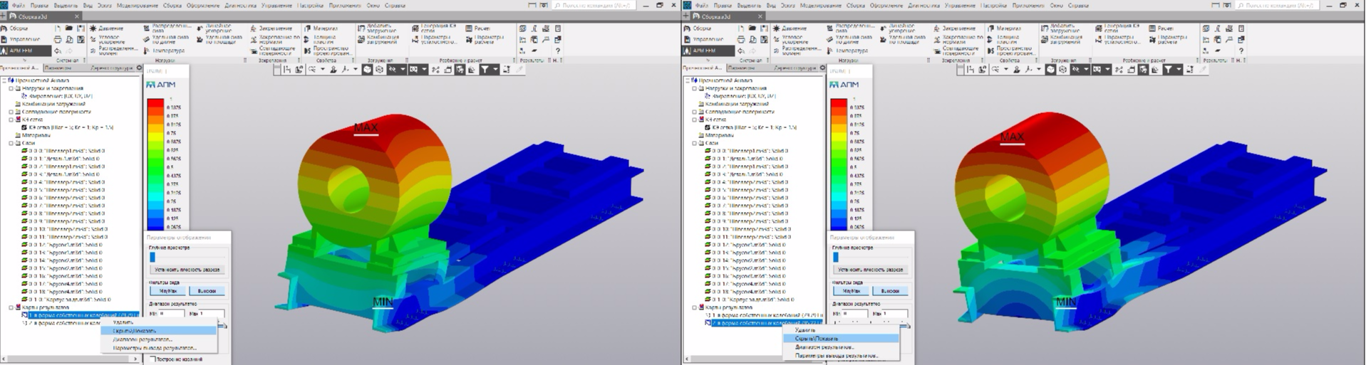
Calculation results in Compass-3D:
Visualization of the first two modes:
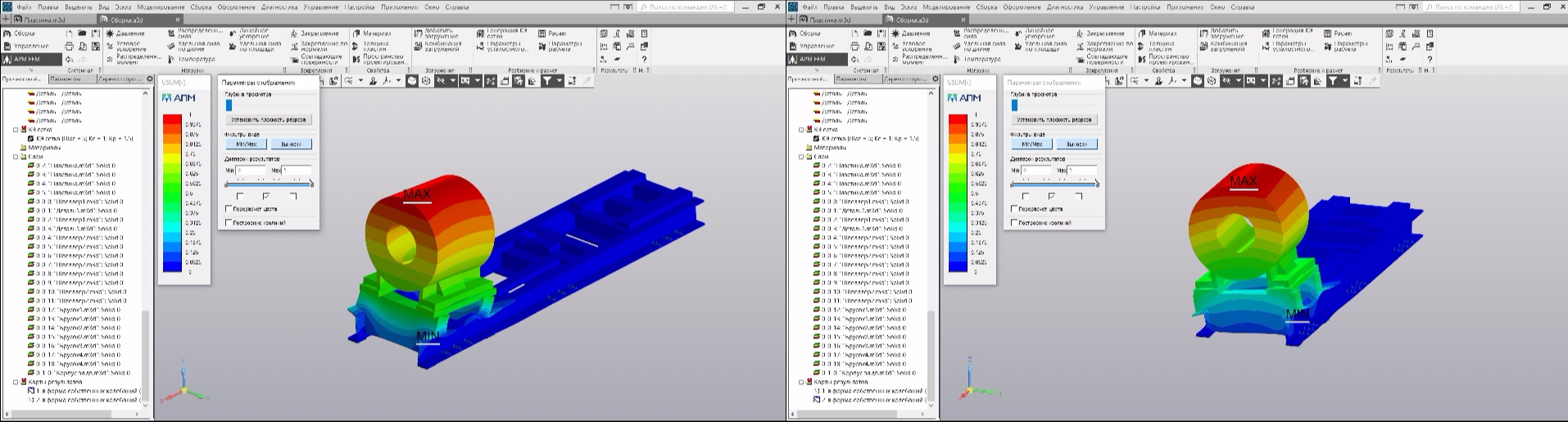
As you can see the directions of vibrations of the singer (left) and the second (right) mode remained the same.
Calculation in ANSYS
Calculation Results:
Visualization of the first oscillation mode:

And the second mod:

Conclusion
The calculation results in Compass-3D and ANSYS are similar, you can use any of these tools. Since the calculation speed and visualization in ANSYS is better, I recommend using the latter.
The disadvantage of modeling vibration modes is the high cost. It took me 40 minutes to take measurements at the place of operation, create a 3D model for about 4 hours, calculate in AMP FEM - 1 hour, calculate in ANSYS - 30 minutes.
The advantage is the visualization of structural vibrations, the ability to quickly model solutions to problems.
As a result, modal analysis confirmed the presence of structural resonance and helped identify the root cause. Further modeling showed that strengthening the fit of the frame under the electric motor should tune the eigenfrequencies of the structure from the double frequency of the 100 Hz network and relieve the electric motor of resonance. The results of this work will be transferred to the owner of the equipment. I really hope that soon I will be able to please you with an article on the results of the planned work.
Добрый день. Очень полезная информация). Можете выложить файл расчета в Ansys.
Здравствуйте, к сожалению дело было пару лет назад и сохранений не осталось. Но воспроизвести аналогичные расчеты вроде не трудно, все шаги описаны.